
How to Connect a Single PLC Module to the Main Processor: Complete 2025 Guide
Meta Description: Learn how to connect PLC modules to main processors with step-by-step instructions, wiring diagrams, and safety protocols. Expert guide for industrial automation engineers.
A single PLC module connects to the main processor through the backplane communication bus, which provides both power and data transfer pathways between the CPU and I/O modules.[1] This physical connection interface enables real-time communication essential for industrial automation systems to function reliably.
Modern industrial automation depends heavily on proper PLC module integration. According to recent industry analysis, automation engineering roles are projected to grow 8% through 2031, significantly faster than average occupations.[2] Understanding module connection procedures is fundamental for anyone working in industrial control systems, from maintenance technicians to automation engineers.
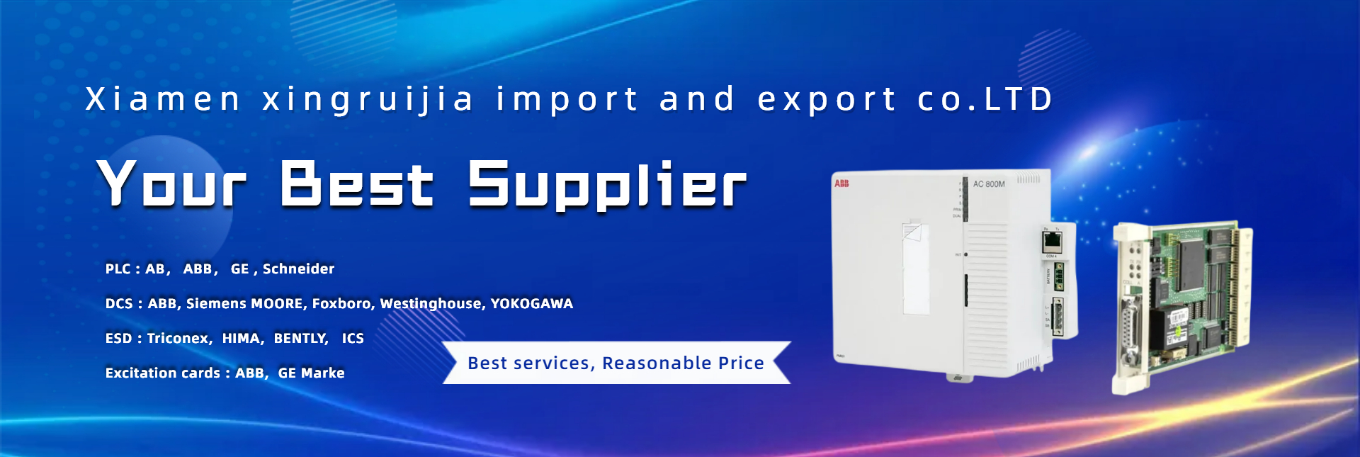
Saul Electric (ebuyplc.com), serving global industrial automation markets with PLC modules from leading manufacturers including ABB, Allen-Bradley, Emerson, and Rockwell ICS Triplex, has compiled this comprehensive guide to help engineers and technicians master single module installation procedures. Whether you’re installing analog input cards, digital output modules, or specialty communication modules, following proper connection protocols ensures system reliability and safety.
Understanding PLC Module Architecture
PLC modules interface with the main processor through a standardized backplane that serves as both a mechanical mounting structure and electrical communication pathway.[1] The backplane contains parallel bus lines that distribute power and facilitate high-speed data exchange between the CPU and connected modules.
Modern PLC systems employ modular architecture that delivers significant advantages over monolithic designs. The modular approach allows engineers to customize system capabilities by selecting specific input/output modules, communication interfaces, and specialized function modules tailored to application requirements.
The main processor, also called the CPU module, executes control logic while coordinating with I/O modules to interface with field devices. Input modules receive signals from sensors, switches, and measurement devices, converting real-world signals into digital data the processor can interpret. Output modules receive digital commands from the processor and convert them to appropriate signal levels to control actuators, motors, valves, and indicator lights.
Key Components in Module-to-Processor Connection:
- Backplane Communication Bus: The physical pathway connecting all modules, typically supporting multiple communication protocols including proprietary high-speed buses and industry-standard protocols like Ethernet/IP. The backplane handles data rates ranging from 12 Mbps for older systems to 1 Gbps or higher for modern platforms.[3]
- Power Distribution System: Integrated power rails within the chassis supply regulated DC voltage to all connected modules. Most industrial PLCs operate on 24V DC logic power, though some systems use 5V or 12V depending on manufacturer specifications.
- Module Slot Configuration: Each chassis slot connects to specific backplane addresses, allowing the processor to identify and communicate with individual modules based on physical location. The processor scans each configured slot sequentially during its normal operating cycle.
- Card Edge Connectors: Physical connection points on both the module and backplane that establish electrical contact when a module is properly seated. These connectors typically feature gold-plated contacts to ensure reliable conductivity in industrial environments.
Saul Electric offers modules compatible with major PLC platforms, including Allen-Bradley ControlLogix systems that feature advanced backplane architectures supporting multiple processors, motion controllers, and I/O modules on a single chassis. The Rockwell ICS Triplex modules available through ebuyplc.com include both standard and redundant configurations for safety-critical applications.
Pre-Installation Requirements and Safety Precautions
Before connecting any PLC module to the main processor, completely de-energize the system and verify zero voltage at the installation point using appropriate test equipment.[4] This critical safety step prevents electric shock hazards and protects sensitive electronic components from damage during installation.
Safety Equipment and Documentation
- Electrostatic discharge (ESD) wrist strap or anti-static mat
- Insulated hand tools appropriate for electrical work
- Voltage testing equipment (multimeter or voltage detector)
- Module-specific installation manual from manufacturer
- System wiring diagrams showing module location and terminations
- Lock-out/tag-out (LOTO) equipment for power isolation
Environmental Considerations
PLC modules contain sensitive electronic components vulnerable to electrostatic discharge and environmental contaminants. According to electrical engineering standards, proper ESD protection is essential when handling any electronic module.[5] Static electricity levels as low as 100 volts can damage CMOS components, though higher voltages typically cause immediate failure.
Verify installation environment meets these conditions:
- Temperature Range: Most industrial PLC modules operate within -40°C to 70°C, though optimal performance occurs at 0°C to 55°C. Check specific module specifications as analog and specialty modules may have narrower operating ranges.
- Humidity Limits: Relative humidity should remain between 5% and 95% non-condensing. Excessive humidity can cause corrosion on connector contacts and circuit board traces.
- Vibration and Shock: Ensure chassis mounting provides adequate mechanical support to withstand industrial vibration levels. Loose mounting can cause intermittent connection failures at backplane connectors.
- Electrical Noise: Position PLC modules away from high-voltage AC lines, variable frequency drives, and welding equipment that generate electromagnetic interference. Maintain minimum separation distances specified in manufacturer documentation.
System Documentation Review
- Module catalog number matches configuration database entry
- Slot location corresponds to software addressing scheme
- Power supply capacity accommodates additional module current draw
- Firmware compatibility between new module and existing processor
- I/O addressing does not conflict with existing module assignments
The extensive catalog of ABB modules and Emerson modules at ebuyplc.com includes specification sheets detailing power requirements and environmental ratings for each module type. Consulting these specifications during planning prevents compatibility issues during installation.
Step-by-Step Physical Connection Procedure
Follow this systematic procedure to connect a single PLC module to the main processor through the backplane communication bus.
- 1. Power Down and Verify De-Energization
- a. Notify all relevant personnel of the planned system shutdown using established communication protocols
- b. Execute lock-out/tag-out procedures at main power disconnect serving the PLC system
- c. Allow 30-60 seconds for internal capacitors to discharge after removing primary power
- d. Use voltage testing equipment to verify 0V at power supply terminals and module connection points
- e. Remove power supply module if chassis design requires complete power isolation during module installation
Critical Safety Note: Some PLC systems maintain voltage on backplane communication lines even when main power is disconnected. Always verify zero voltage before touching backplane connectors or module contacts.
- 2. Prepare Module and Installation Slot
- a. Remove new module from protective anti-static packaging only after grounding yourself with ESD wrist strap
- b. Visually inspect module backplane connector for bent pins, foreign material, or damage
- c. Check chassis slot for dust, debris, or damaged connector contacts using flashlight
- d. Clean slot connector contacts with approved electronic contact cleaner if contamination is present
- e. Remove slot blanking plate or placeholder module if present, storing removed components properly
For systems using ControlLogix or similar modular platforms, each slot features a spring-loaded connector cover that protects unused positions. Follow manufacturer instructions for proper cover removal as documented in installation manuals available for systems from suppliers like Rockwell automation platforms.[6]
- 3. Insert Module into Chassis Slot
- a. Orient module with component side facing correct direction per manufacturer labeling
- b. Align module card edge connector with chassis slot backplane connector
- c. Gently slide module into slot while maintaining perpendicular alignment to backplane
- d. Apply firm, even pressure on both top and bottom of module faceplate
- e. Push until module seats completely and latching mechanism engages with audible click
Installation Verification: The module should sit flush with adjacent modules, and status indicators (if present) should be in their non-powered state. Any resistance during insertion indicates misalignment—never force a module as this damages both module and backplane connectors.
- 4. Secure Module Mechanically
- a. Verify module retention clip or latch fully engages with chassis mounting rail
- b. For screw-secured modules, tighten mounting screws to manufacturer-specified torque
- c. Check that module cannot be removed by gentle upward pulling
- d. Confirm module sits level with no visible gaps at backplane connection point
Most modern PLC chassis use spring-clip retention systems that automatically lock modules in place. Older systems may require manual screw tightening. The Honeywell modules and Foxboro modules available through ebuyplc.com feature various retention mechanisms depending on platform generation.
- 5. Connect Field Wiring (If Applicable)
For I/O modules requiring field device connections:
- a. Identify field wire bundle corresponding to new module location
- b. Verify wire labels match terminal assignments in system documentation
- c. Strip wire insulation to length specified in termination instructions (typically 6-8mm)
- d. Insert wires into spring-clamp or screw terminals following torque specifications
- e. Verify each connection by gently tugging wire to confirm mechanical retention
- f. Install wire strain relief mechanisms to prevent mechanical stress on terminals
Wiring Best Practices: Route signal wires separately from power cables, maintain consistent polarity on DC circuits, and use shielded cable for analog signals with shield grounding at one end only to prevent ground loops.
- 6. Restore Power and Verify Module Recognition
- a. Remove lock-out/tag-out devices after confirming all personnel are clear of equipment
- b. Restore power to PLC system using normal startup procedures
- c. Observe module status indicators during power-up sequence
- d. Verify processor recognizes new module by checking chassis configuration display
- e. Review diagnostic buffers for any fault codes related to new module
Troubleshooting Initial Power-Up: If the processor does not recognize the newly installed module, verify the module is fully seated, check that chassis slot is configured in software, and confirm module type matches configuration database entry.
Saul Electric provides technical support for module integration across all major platforms, with expertise in GE modules, Schneider modules, and other industrial automation components available at ebuyplc.com.
Software Configuration and Module Addressing
After physical installation, configure the PLC programming software to recognize the new module and establish proper I/O addressing.[7]
Programming Software Configuration Steps
- Hardware Tree Addition: Open your PLC programming software (Studio 5000, TIA Portal, Unity Pro, etc.) and navigate to the hardware configuration section. Add a new module entry to the chassis configuration tree, specifying exact module catalog number and slot location.
- Parameter Configuration: Set module-specific parameters including: Scan rate or Requested Packet Interval (RPI) for I/O updates; Input filter times for digital inputs; Engineering unit scaling for analog I/O channels; Alarm and warning thresholds.
- Address Assignment: Configure I/O addressing scheme consistent with program logic: Verify tag names or address assignments match existing program documentation; For fixed addressing confirm base addresses do not overlap; For tag-based systems create descriptive tag names.
- Fault Configuration: Enable appropriate diagnostic features: Module fault detection and response actions; Connection timeout values; Health monitoring parameters for critical I/O points.
Firmware Compatibility Verification
Check that new module firmware revision is compatible with processor firmware. Mismatched firmware versions can cause communication failures or unexpected behavior. Most programming software tools display firmware version for each module and flag compatibility issues during download operations.
For processors from manufacturers like those available through ebuyplc.com, including Bently modules and Yokogawa modules, firmware upgrade procedures vary by platform. Consult manufacturer documentation before attempting firmware updates on production systems.
Configuration Download and Validation
- Compile program to verify no syntax or addressing errors exist
- Download updated configuration to processor, selecting appropriate download mode
- Verify module status indicators show normal operation (typically solid green LED)
- Monitor I/O data tables to confirm signal flow from input modules and command execution to output modules
- Test module functionality by forcing inputs and observing corresponding program logic response
Safety Verification: For output modules controlling critical equipment, test fail-safe behavior by intentionally creating fault conditions to verify outputs respond appropriately. This validation ensures safety circuits function correctly before placing equipment in automatic mode.
Common Connection Issues and Troubleshooting
Module recognition failures typically result from incomplete seating, configuration mismatches, or compatibility issues between module and processor firmware versions.[8]
Module Not Detected by Processor
Symptom: Processor displays “Module Missing” or “Module Fault” for newly installed module
- Verify module is completely seated—remove and reinstall with firm pressure
- Check chassis slot configuration in programming software matches physical slot location
- Confirm module catalog number in software configuration exactly matches physical module
- Inspect backplane connector pins for damage or contamination
- Test suspect slot by installing known-good module to isolate chassis vs. module fault
- Verify power supply capacity is sufficient for all installed modules
Communication Errors and Intermittent Faults
Symptom: Module connects initially but displays intermittent fault indicators or loses communication periodically
- Check module retention mechanism is fully engaged—loose modules cause intermittent connection loss
- Verify adequate chassis grounding to prevent electrical noise coupling into backplane signals
- Measure backplane supply voltages under load—voltage drops below specification cause communication errors
- Review diagnostic logs for specific error codes identifying root cause
- Check for sources of electromagnetic interference near PLC chassis
I/O Signal Issues
Symptom: Module communicates properly but field device signals do not function correctly
- Verify field wiring connections correspond to terminal assignments in documentation
- Check for proper voltage levels at input terminals using multimeter
- Confirm output commands reach terminal blocks by measuring voltage during forced output tests
- Review module configuration parameters—incorrect scaling or filtering settings affect signal quality
- Test field devices independently to isolate device failures from module issues
Firmware Compatibility Problems
- Check module firmware revision against processor compatibility matrix
- Update module firmware using manufacturer-provided update tools
- Verify processor firmware is current version supporting latest module releases
- Review release notes for both processor and module firmware identifying known issues
Advanced Connection Considerations
Hot-Swappable Modules
Some industrial PLC platforms support hot-swap capability, allowing module replacement without powering down the entire system. Hot-swap modules feature specialized circuitry that prevents backplane disruption during insertion and removal.
Hot-swap procedure requires:
- 1. Verify chassis and module support hot-swap operation per manufacturer specifications
- 2. Use programming software to place target slot in “inhibit” mode before removal
- 3. Wait for module status to indicate safe removal state
- 4. Remove old module and install replacement following standard procedures
- 5. Use software to enable new module and restore normal operation
Critical limitation: Only certain module types support hot-swap. Processor modules, power supplies, and some specialized modules require full system shutdown for replacement.
Redundant Module Configuration
Safety-critical applications often employ redundant PLC architectures where duplicate modules provide backup capability. Redundant systems require specialized connection procedures:
Primary and backup modules connect to separate backplane segments or redundant chassis, with synchronization occurring through dedicated communication links. Configuration software establishes primary/secondary relationships and defines failover behavior.
Installation sequence:
- 1. Install and configure primary module following standard procedures
- 2. Install secondary module in designated redundant slot
- 3. Configure redundancy parameters defining synchronization timing and failover conditions
- 4. Verify automatic switchover by testing primary module failure scenarios
- 5. Monitor redundancy status indicators during normal operation
Safety platforms including ICS Triplex systems available through ICS Triplex modules at ebuyplc.com implement triple modular redundant architectures for ultimate reliability.
Network Communication Modules
Modules providing network connectivity (Ethernet/IP, Profinet, Modbus TCP) require additional configuration beyond basic I/O modules:
Network parameters include IP address assignment, subnet mask, gateway configuration, and security settings. Some protocols require configuration of device profiles or Electronic Data Sheets (EDS files) defining communication capabilities.
Installation considerations:
- 1. Coordinate IP addressing with network administrator to avoid conflicts
- 2. Configure appropriate network security features including firewalls and authentication
- 3. Test network connectivity using built-in diagnostic tools before placing system in production
- 4. Document network topology including switch ports and VLAN assignments
Maintenance and Long-Term Reliability
Proper module connection ensures immediate functionality, but long-term reliability requires ongoing maintenance protocols.
Periodic Inspection Schedule
Quarterly checks:
- Visual inspection of status indicator LEDs identifying abnormal conditions
- Review diagnostic buffers for intermittent fault codes
- Verify environmental conditions remain within specifications
Annual maintenance:
- Inspect backplane connectors for signs of corrosion or discoloration
- Re-seat all modules to ensure positive connection retention
- Clean chassis interior using approved methods (filtered compressed air or vacuum)
- Verify backup configurations match current installed hardware
Spare Module Management
Maintain appropriate spare module inventory: critical spares include modules supporting essential process control functions where failure causes production loss. Stock exact catalog number replacements to ensure compatibility. Store spare modules in anti-static packaging within temperature and humidity controlled environment.
Configuration backup: Maintain module configuration files in secure storage with revision control. This enables rapid replacement and configuration restoration following module failure.
Documentation Updates
- As-built electrical drawings showing current module assignments
- I/O address cross-reference listing signal names and terminal locations
- Configuration file versions stored in change management system
- Maintenance logs recording all module installations, removals, and troubleshooting activities
The comprehensive product range at ebuyplc.com includes modules from over 30 major automation manufacturers, enabling standardized spare parts programs across multi-vendor installations. Explore featured modules and manufacturer-specific categories to identify replacement options for your system.
FAQ
Q: Can I install a PLC module while the system is powered on?
A: Only modules specifically rated for hot-swap installation can be installed while powered. Most standard I/O modules require complete system shutdown to prevent backplane communication disruption and protect sensitive electronics from voltage transients during insertion. Always consult manufacturer documentation before attempting hot module replacement.[4]
Q: How do I know if my PLC module is properly seated in the backplane?
A: A properly seated module sits flush with adjacent modules, the retention clip or latch fully engages with an audible click, status indicators respond during power-up, and the processor software recognizes the module in the chassis configuration display. Physical inspection should show no visible gaps at the backplane connection point.[5]
Q: What causes a module to show a fault status immediately after installation?
A: Common causes include firmware version incompatibility between module and processor, incorrect catalog number specified in software configuration, insufficient power supply capacity, defective module or backplane connector, and configuration parameter settings outside module capabilities. Systematic troubleshooting following manufacturer diagnostic procedures identifies the specific fault condition.[8]
Q: Do I need special tools to install PLC modules?
A: Most PLC modules install without tools using spring-clip retention systems. However, you need proper ESD protection (wrist strap or anti-static mat), voltage testing equipment to verify de-energization, and standard hand tools if field wiring termination is required. Specialty modules may require manufacturer-specific tools for configuration or firmware updates.
Q: How often should I inspect module connections in a running PLC system?
A: Quarterly visual inspection of status indicators and annual physical inspection during scheduled maintenance shutdowns provides adequate monitoring for typical industrial environments. Critical applications or harsh environments may require more frequent inspection. Monitor diagnostic logs continuously for intermittent fault conditions indicating developing connection problems.
Conclusion
Connecting a single PLC module to the main processor through proper backplane integration ensures reliable industrial automation system operation. Following systematic installation procedures—from initial safety verification through software configuration and testing—minimizes commissioning time while establishing a foundation for long-term reliability.
The modular architecture of modern PLC systems provides flexibility to customize control system capabilities, but proper connection techniques are essential to realize this advantage. Whether installing basic digital I/O modules or sophisticated specialty modules, attention to detail during physical installation, careful software configuration, and thorough testing procedures deliver dependable results.
As industrial automation systems continue evolving toward greater connectivity and intelligence, understanding fundamental module connection principles remains critical for automation professionals. The techniques covered in this guide apply across manufacturer platforms, though specific procedures vary by PLC family.
Expert Support for Module Integration
Saul Electric (ebuyplc.com) provides comprehensive support for PLC module integration across all major industrial automation platforms. Our extensive inventory includes modules from ABB, Allen-Bradley, Emerson, GE, Honeywell, Rockwell, Schneider Electric, Siemens, and dozens of additional manufacturers.
Explore our complete module selection at www.ebuyplc.com to find compatible components for your automation system. Our technical team offers application assistance to ensure proper module selection and integration for your specific requirements.
For module sourcing, technical questions, or integration support, contact Saul Electric through our website or explore our product categories including specialty modules for safety systems, motion control, and advanced communication protocols.
References
- [1] Control.com, “All About PLCs: Input/Output Modules,” 2024. https://control.com/technical-articles/all-about-plcs-input-output-modules/
- [2] PLC Programming, “Complete PLC Programming Guide 2025,” 2025. https://plcprogramming.io/blog/complete-plc-programming-guide-2025
- [3] PLC Programming Glossary, “Backplane – Complete Definition & Guide,” 2025. https://plcprogramming.io/glossary/backplane
- [4] Southern Electrical, “What Are the Steps Involved in Installing a PLC System?” 2025. https://www.southernelectrical.com/steps-involved-in-installing-a-plc-system/
- [5] Electrical Engineering Portal, “Guidelines for PLC installation, wiring and connection precautions,” 2025. https://electrical-engineering-portal.com/plc-installation-wiring-connection-precautions
- [6] Rockwell Automation Literature, “ControlLogix DC Digital I/O Modules Installation Instructions,” 2025. https://literature.rockwellautomation.com/idc/groups/literature/documents/in/1756-in062_-en-p.pdf
- [7] Automation Direct, “Adding Modules,” 2025. https://cdn.automationdirect.com/static/helpfiles/ls_plc/Content/C_ProcedureTopics/LP101-5.htm
- [8] AIVON, “PLC Installation and Commissioning Procedure,” 2025. https://www.aivon.com/blog/plc-installation-and-commissioning-procedure/
Tags: #PLCModule #IndustrialAutomation #PLCInstallation #BackplaneConnection #ModuleConfiguration #AutomationEngineering #PLCProcessor #IOModules #PLCWiring #IndustrialControl
© 2025 Saul Electric (ebuyplc.com) – Expert guide for automation professionals
Post time: Mar-04-2026