

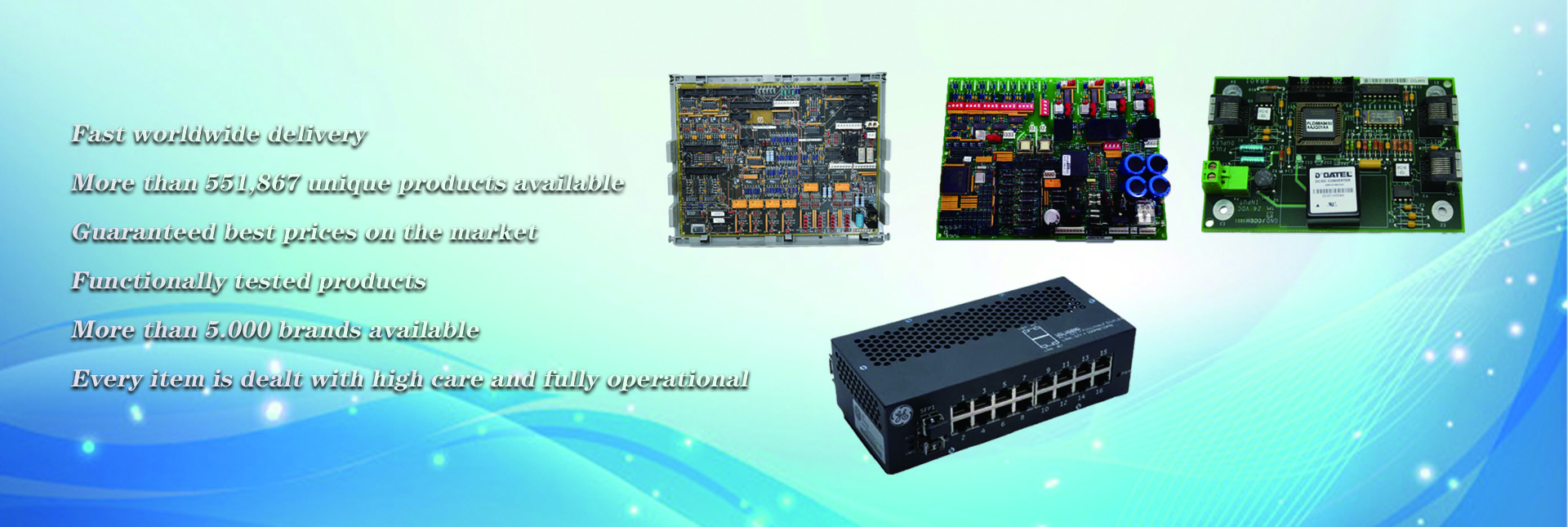
Analog signal processing modules are the critical layer that connects a PLC’s discrete control logic to the continuous, variable physical conditions that define most industrial processes. Unlike digital signals that only carry simple on or off states, analog signals carry real-time measurements of temperature, pressure, flow rate, position, vibration, and other variables that change smoothly across a wide range of values. These modules convert faint, variable electrical signals from field sensors into precise, digitally encoded data the control system can use to make fine-tuned adjustments that keep processes stable, efficient, and within safe operating limits.
Signal conversion fundamentals and scaling architecture
Every analog processing module relies on high-resolution analog-to-digital and digital-to-analog conversion stages that translate between the continuous electrical world of field devices and the discrete numerical logic of the PLC. The resolution of this conversion process determines how finely the module can detect small changes in the incoming signal, which directly impacts the system’s ability to respond to subtle process shifts before they develop into larger deviations. Properly designed modules include built-in reference circuits that stabilize conversion accuracy across wide swings in operating temperature, preventing drift that would otherwise make readings less reliable as the module warms up or cools down during normal plant operation.
Scaling is the core step that maps the raw numerical value generated by the conversion process to real-world engineering units that operators and control logic can interpret. For example, a standard industrial signal range from a pressure transmitter gets translated directly into bar, psi, or kilopascal values that match the physical measurement the sensor is designed to capture. Teams that document every scaling formula clearly, and cross-reference it against the sensor’s calibrated range, eliminate mismatches that can cause the control system to misinterpret measurements and trigger incorrect process adjustments. This documentation also creates a shared reference for maintenance teams, so new technicians do not have to reverse-engineer scaling logic during emergency troubleshooting.
Wiring and interference reduction for stable measurements
More than 60 percent of all analog signal faults in industrial installations trace back to wiring mistakes that introduce noise, ground loops, or unintended signal loss into the measurement path. Field technicians need to route analog signal cables completely separate from high-voltage power lines, variable frequency drive output cables, and other sources of strong electromagnetic radiation that can corrupt low-level measurement signals. Shielded twisted pair cabling is standard for nearly all analog runs, and the shield layer must be grounded at exactly one consistent point, usually at the sensor end for current loop signals or at the PLC cabinet end for low-voltage voltage signals, to prevent circulating ground loop currents that add unpredictable drift and noise to every reading.
Different analog signal types have unique wiring requirements that must be followed to avoid damage and poor performance. Current loop signals are far more resistant to voltage drop over long cable runs, making them ideal for sensors located hundreds of meters away from the control cabinet, while low-level millivolt signals from thermocouples and load cells require extra care to avoid even tiny amounts of induced noise. Teams that clearly label every analog channel at both the module terminal strip and the sensor end, and separate analog signal grounds from high-current power grounds in the cabinet, eliminate most of the common avoidable faults that cause intermittent, hard-to-reproduce measurement drift.
Filtering, calibration, and long-term performance management
Even with perfect wiring, industrial environments expose analog signals to transient noise spikes from switching relays, large motor startups, and nearby welding operations that can create temporary false readings. Most analog processing modules support configurable digital filtering routines, such as moving average filters over a small set of consecutive samples, that smooth out these transient disturbances without adding unnecessary lag to the measurement response. Tuning filter strength to match the specific process dynamics ensures that fast, critical changes are still detected quickly, while random noise spikes that do not reflect real physical process conditions are suppressed before they can reach the control logic.
Regular scheduled calibration is essential to maintain long-term measurement accuracy, as component aging and years of exposure to electrical transients can create small offsets between the actual physical value at the sensor and the value reported by the module. Teams use traceable reference signal sources to inject precise known values into each channel, verify that the reading falls within the acceptable accuracy tolerance, and make minor adjustments if any drift has developed over time. These calibration results should be logged and stored alongside the original scaling documentation, creating a full performance history for every channel that helps teams spot slow developing trends before they cause process instability or unplanned downtime.
Post time: Nov-03-2026