Product Overview
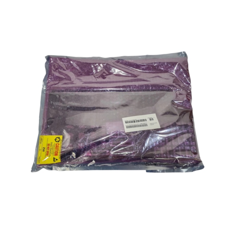
810-073479-005 is a critical RF power transmission and distribution component designed by Lam Research for its advanced plasma etching and deposition systems. Specifically, it functions as an RF Feedthrough or RF Power Splitter. The prefix “810” in Lam Research’s spare part system typically identifies this unit as RF transmission and matching hardware.
The core function of the 810-073479-005 is to serve as a physical pathway for transmitting RF energy from the atmospheric environment (or equipment exterior) into the high-vacuum reaction chamber. Additionally, it distributes single or multiple channels of RF power at precise ratios to different electrodes inside the chamber, including the lower electrode, upper electrode, and electrostatic chuck (ESC). This component meets three stringent technical requirements: low-loss transmission of high-power RF signals, ultra-high airtightness for vacuum environments, and precise impedance matching (standard 50Ω).
Product Specifications
|
Parameter Name
|
Parameter Value
|
|
Product Model
|
810-073479-005
|
|
Manufacturer
|
Lam Research
|
|
Product Type
|
RF Feedthrough / RF Power Splitter
|
|
Applicable Systems
|
Lam Research 2300 Series and Versys Series Etch/Deposition Tools
|
|
Operating Frequency
|
Typically supports industrial bands of 2 MHz, 27 MHz, 60 MHz
|
|
Maximum Input Power
|
Compatible with 3 kW to 5 kW RF generators
|
|
Characteristic Impedance
|
50 Ω
|
|
Channel Quantity
|
Multi-channel (typical 2 or 4 output channels)
|
|
Vacuum Interface
|
Standard CF (ConFlat) flange, including CF35, CF50, CF100
|
|
Atmospheric-Side RF Connector
|
Customized 7/16 DIN or Type N connector
|
|
Material
|
High-purity 316L stainless steel (vacuum side), silver-plated copper alloy (conductor), alumina ceramic (insulation)
|
|
Leak Rate
|
< 1.0 x 10⁻⁹ mbar·L/s (Helium Leak Test)
|
|
Installation Method
|
Fixed to reaction chamber walls or adapters via standard CF flanges
|
Structure and Composition
The 810-073479-005 is a precision component that integrates high-power RF engineering and ultra-high vacuum technology. Its internal structure consists of three core parts: an atmospheric-side interface, a vacuum sealing and insulation unit, and a vacuum-side power distribution network.
The atmospheric-side interface adopts standard coaxial connectors (e.g., 7/16 DIN) to connect RF cables from matching networks or generators. The core sealing and insulation unit uses high-purity alumina (Al₂O₃) ceramic as the insulating medium, which features high dielectric strength, excellent RF wave transmission performance, and superior mechanical strength. The ceramic and metal flange are connected via vacuum brazing or compression sealing technology to achieve ultra-high airtightness, forming a reliable barrier between vacuum and atmospheric environments.
The central conductive conductor is made of high-conductivity copper alloy with precision silver or gold plating to maximize RF transmission efficiency. On the vacuum side, the internal conductor extends to a precisely engineered power distribution network. Adopting coaxial or stripline structures, the network accurately calculates electrical length and characteristic impedance to distribute input RF energy to multiple output ports at process-specific ratios (1:1 or asymmetric ratios) for connection to different chamber electrodes. The overall design of the 810-073479-005 ensures consistent impedance continuity and phase uniformity throughout the entire RF transmission path.
Key Features and Advantages
Superior Vacuum Integrity and Long Service Life
The core advantage of the 810-073479-005 lies in its ultra-reliable vacuum sealing performance. Adopting precision brazing technology for alumina ceramic and metal flanges, it maintains an extremely low leak rate below 1.0 x 10⁻⁹ mbar·L/s long-term, even under baking temperatures of hundreds of degrees Celsius. This is critical for stabilizing the base vacuum level and process gas purity of reaction chambers, effectively preventing wafer oxidation, particle contamination, and process abnormalities caused by air leakage.
Optimized Power Distribution and Phase Consistency
As a professional power splitter, the 810-073479-005 features a finely tuned internal structure that ensures high amplitude balance and phase consistency of RF power at all output ports. It is particularly suitable for multi-electrode and large-area electrode chamber designs, enabling uniform plasma sheath formation across the entire wafer surface. This delivers excellent etching rate uniformity and precise CD control, significantly improving wafer yield.
Low-Loss Transmission and High Power Bearing Capacity
Equipped with low-resistivity silver-plated conductors and low-loss ceramic insulating materials, the component achieves ultra-low RF insertion loss, ensuring most RF energy is efficiently transmitted to the reaction chamber rather than dissipated as heat. Meanwhile, its robust mechanical structure and optimized heat dissipation design support long-term stable operation under continuous RF power of several kilowatts, adapting to harsh semiconductor process conditions.
Application Fields
The 810-073479-005 is exclusively applied to plasma process equipment in front-end semiconductor manufacturing. It is widely integrated into Lam Research 2300 Series etchers (including Kiyo dielectric etching and Flex conductor etching series) and partial Versys Series deposition equipment, serving as a key interface component connecting internal equipment RF transmission cables and reaction chambers.
It transmits RF power from matching networks into the chamber through vacuum feedthrough structures and distributes power to different zones of the lower electrode (bias generation), upper electrode (plasma source generation), and electrostatic chuck (ESC) according to process requirements. Its performance directly affects the ion energy and flux distribution on wafer surfaces, determining core process indicators including etching rate, selectivity, sidewall profile, and deposition uniformity. For manufacturers of advanced logic chips, DRAM, and 3D NAND flash memory, the high performance of 810-073479-005 is essential for strict process control, yield improvement, and production cost reduction.
Related Products
810-073479-004: Same-series RF feedthrough structure with different channel quantities or power distribution ratios to adapt to diverse chamber designs.
810-002895-233: Lam Research RF power distribution and matching component, located upstream of 810-073479-005, responsible for secondary power distribution after matching network output.
V7668A-132L00W02 (605-064676-R008): RF impedance matching network component, with its output terminal connected to the atmospheric-side interface of 810-073479-005 via RF cables.
800-109736-003: High-power RF cable matched with the RF feedthrough structure, featuring customized length and phase characteristics for connecting matching networks and 810-073479-005.
853-257153-232: High-precision RF directional coupler/sensor component, generally installed upstream of 810-073479-005 to monitor chamber feed-in power and reflected power.
852-002374-801: Special installation and maintenance kit for 810-073479-005, including replacement metal sealing gaskets (e.g., OFHC copper gaskets), fastening screws, and cleaning tools.
830-101240-018: Dedicated RF path calibration tool for Lam Research equipment, used to verify the transmission characteristics of the entire RF feedthrough path after 810-073479-005 replacement.
Installation and Maintenance
Pre-installation Preparation
The installation of the 810-073479-005 requires extremely high cleanliness and operational accuracy, and must be performed by Lam Research certified engineers in a cleanroom environment. Before operation, ensure the equipment is fully shut down and powered off, and confirm the reaction chamber is vented to atmospheric pressure and in a safe state.
All installation procedures must comply with ultra-high vacuum operation specifications. Prepare clean dust-free cloths, isopropyl alcohol (IPA), and high-purity nitrogen purge guns. Inspect the flange sealing surfaces of new and old components for scratches or damage, and prepare new high-purity metal sealing gaskets (copper or silver-plated gaskets).
During installation, fasten flange bolts symmetrically and evenly with standard torque to achieve reliable airtight sealing. Use a dedicated torque wrench for RF connector installation to avoid over-tightening and component damage.