Welcome to our websites!

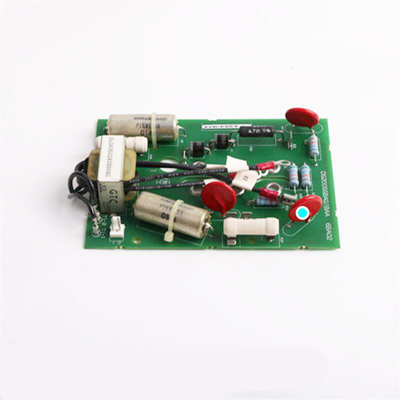
GE Alstom L54E2900WH00 Control Module
GE Alstom L54E2900WH00
1. Product Overview
GE Alstom L54E2900WH00 is a core control module launched by Alstom (now part of GE/Alstom’s Microrec system), usually associated with the BCSA1 (L54E2900WH00) series. As a key component of the excitation control system for large generator sets, this product is mainly responsible for processing the current and voltage signals of the motor to ensure the stable operation of the power grid.
______________________________________________________________________________________________________
2. Core Parameters
|
Parameter Category
|
Specific Parameters
|
Description
|
|---|---|---|
|
Product Model
|
L54E2900WH00
|
Corresponds to BCSA1 (BCSA1) model
|
|
Function Positioning
|
Excitation Control Module
|
Responsible for precise control of excitation current
|
|
Main Interface
|
MDEX1 Card (Microrec K4.1 System)
|
Standard interface for communication with the main controller
|
|
Voltage Specification
|
220-240V AC / 100-125V AC
|
Multiple power supply voltage options
|
|
Communication Protocol
|
Profibus / VME
|
Supports industrial standard fieldbus protocols
|
|
Environmental Adaptability
|
-40°C – +85°C
|
Suitable for harsh industrial environments
|
______________________________________________________________________________________________________
3. Product Features
High Reliability and Redundancy
Designed with industrial-grade components, it has extremely high anti-interference capability, ensuring long-term stable operation in harsh environments.
Precise Excitation Control
Supports precise current and voltage measurement and processing, which can quickly respond to power grid fluctuations and maintain voltage stability.
Modularity and Maintainability
Adopting a standard card structure, it supports quick plug-and-play maintenance, which greatly reduces operation and maintenance costs.
Strong Compatibility
Highly compatible with the Alstom Microrec K4.1 system and its HMI (Human-Machine Interface), supporting a variety of industrial communication protocols.
______________________________________________________________________________________________________
4. Structure and Composition
As a part of the Alstom Microrec K4.1 system, the module usually includes the following key components in its internal structure:
Main Control Chip
Responsible for the core calculation of the excitation algorithm to ensure the precise output of the excitation current.
Signal Acquisition Module
Receives analog signals from Voltage Transformers (VT) and Current Transformers (CT), and performs amplification and filtering processing.
Communication Interface Unit
Provides MDEX1 interface, Profibus or VME bus interface for data exchange with upper computers or other control modules.
Power Management Module
Converts the industrial power grid voltage into internal logic level to ensure stable power supply for each circuit.
Human-Machine Interface (HMI)
Links with Alstom HMI or operator station to display operating status, alarm information and parameter settings in real time.
______________________________________________________________________________________________________
5. Typical Application Fields
Power Plants
As the core controller of the synchronous generator excitation system, it is widely used in generator sets of thermal power plants, hydropower plants and nuclear power plants.
Large-Scale Industrial Control Systems
Used in heavy industry fields such as petrochemical and metallurgy that require precise motor control.
Rail Transit
In some high-voltage direct current (HVDC) power supply or electrified railway systems, it is used for excitation management of traction motors.
______________________________________________________________________________________________________
6. Installation and Maintenance Guide
Installation Steps
Physical Installation
Insert the L54E2900WH00 card into the dedicated slot of the Alstom Microrec K4.1 control system. This process usually does not require additional wiring and adopts a plug-and-play design.
Power Connection
Confirm that the power supply voltage (220-240V AC or 100-125V AC) meets the module specifications, and connect it to the power bus of the system.
Signal Wiring
Connect the secondary side signal wires of the Voltage Transformer (VT) and Current Transformer (CT) to the corresponding analog input ports of the module.
Communication Configuration
Configure the network between the module and the upper computer (SCADA) or HMI through the MDEX1 card or VME bus.
————————————————————————————————————-
If you would like to learn more about our products and services, please feel free to contact us at any time!
- Sales Manager : Jinny
- Email : sales5@xrjdcs.com
- Whatsapp/Mobile:+86 15359273791
Global renowned brand cooperation
ABB 丨 GE 丨Allen Bradley 丨 Honeywell 丨 Emerson 丨 Bently Nevada 丨 Westinghouse
Triconex 丨 Foxboro 丨 ICS Triplex 丨 Hima 丨 Schneider 丨 Yokogawa 丨 Woodward
—————————————————————————————
Company Introduction
We are a high-tech enterprise with years of professional experience in the sales of spare parts for large-scale imported systems (Distributed Control Systems, Programmable Logic Controllers, Redundant Fault-Tolerant Control Systems, Robot Systems) and system integration. Our main brands include ABB, Foxboro, Triconex, Bently Nevada, Ovation, Motorola, Xycom, A-B, Schneider, GE Fanuc, Yaskawa, Woodward and other imported automation system spare parts.
Professionalism and Experience
We have rich experience and professional technical accumulation in the industry, enabling us to provide customers with high-quality products and services. We focus on technological research and development as well as innovation, and have a complete production line and quality control system to ensure the reliability and durability of each product.
Customer-Oriented Service
We attach great importance to communication with customers and can provide customized solutions according to their needs. Whether it is pre-sales consultation or after-sales service, we always take customers as the center, providing timely response and professional support to ensure the best customer experience.
Product Diversity
Our product line is rich, covering multiple fields, and can meet the diverse needs of different customers. Whether it is large-scale production or personalized customization, we can provide high-quality solutions to ensure the high cost performance of products.
Advanced Technology and Equipment
We have advanced production equipment and technological processes, and constantly improve our technical level to maintain market competitiveness. Through continuous innovation and technological improvement, we can produce products with more market competitiveness.
Superior Geographical Location
Located in Xiamen, we benefit from the city’s superior geographical location and convenient transportation and logistics network, which enables us to respond to the needs of domestic and foreign customers more quickly and efficiently, and shorten the delivery time.
Good Corporate Reputation
We enjoy a good reputation in the industry, and have won the trust and long-term cooperative relations of many customers with an honest and pragmatic attitude.
Write your message here and send it to us