Welcome to our websites!


GE DS3800NPSR1A1A Core Circuit Board
GE DS3800NPSR1A1A
GE DS3800NPSR1A1A is a core circuit board under the Speedtronic Mark IV series (also known as the GE Fanuc 900 series) of General Electric (GE for short). The main function of this board is to provide stable DC power for the system, and it is one of the extremely important “heart” components in the Speedtronic Mark IV series.
______________________________________________________________________________________________
Core Parameters
|
Parameter
|
Description
|
|---|---|
|
Model
|
DS3800NPSR1A1A
|
|
Type
|
Power Supply Card
|
|
Applicable System
|
Speedtronic Mark IV / GE Fanuc 900 Series
|
|
Output Voltage
|
5V/24V DC (specific voltage depends on system configuration)
|
|
Maximum Power
|
1000W
|
|
Power Supply Range
|
180-260VAC (supply voltage)
|
|
Features
|
0.5A output current, 5/48 VDC output, 32 PT (points)
|
|
Terminals
|
Long black connection port at the bottom (marked 10 to 80, interval 10)
|
______________________________________________________________________________________________
Product Features
Stable and Reliable Power Output
Adopting high-quality semiconductor components (such as F28S05/1000Z), it provides a continuous output current of 0.5A, which can effectively drive the PLC host and its external I/O modules.
Easy Maintenance and Fault Diagnosis
The board is equipped with LED indicators (orange LED) and multiple test points, which facilitate on-site engineers to quickly diagnose power supply faults.
Strong Compatibility
This board is a standard component of the Speedtronic Mark IV series, and is widely compatible with various main control boards and I/O modules of the GE Fanuc 900 series.
______________________________________________________________________________________________
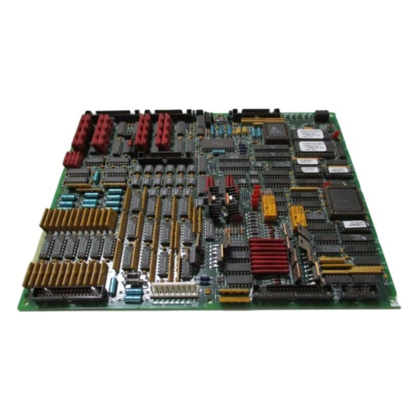
Structure and Composition
Semiconductor Power Components
Two black square semiconductors (marked F28S05/1000Z), which are the main power conversion cores.
Capacitor Array
Including capacitors of different specifications (such as C2, C12, C3, C13), which are responsible for smoothing power ripples and transient suppression.
Power Output Port
A long black connection port marked 10, 20, 30…80 is set at the bottom of the board, which is responsible for distributing power to each module.
Auxiliary Components
Including integrated circuits, transistors, LED indicators and multiple test points, which facilitate on-site detection and debugging.
______________________________________________________________________________________________
Application Fields
Power Plants
As the power core of the unit control system (GCU), it provides key power for the main control system.
Industrial Automation
Widely used in the GE Fanuc 900 series DCS system to provide stable power support for the control system.
Other Fields
It may also be used in the control center of large-scale HVAC (Heating, Ventilation and Air Conditioning) systems, as well as other industrial sites that require high-reliability PLC control.
______________________________________________________________________________________________
Installation and Maintenance
Installation Points
Fixing and Grounding
During installation, the board must be firmly fixed in the cabinet, and the grounding screws at the bottom must be tightened to avoid electromagnetic interference.
Power Line Connection
Connect the power line according to the marking of the terminal (10-80), and ensure that the voltage of each power output (such as 5V or 24V) is correct.
Static Electricity Avoidance
Since there are precision semiconductor components inside the board, installers should wear anti-static wristbands to avoid component damage caused by static electricity.
______________________________________________________________________________________________
Maintenance and Common Faults
Cleaning and Dust Removal
After long-term use, dust may accumulate inside the board. The board should be cleaned regularly with a clean soft brush or compressed air to avoid dust affecting heat dissipation.
Component Replacement
If there is unstable power supply or board damage, it is necessary to replace the semiconductor components or capacitors on the board. Due to the involvement of high voltage, replacement must be performed by professional engineers.
Voltage Monitoring
During maintenance, a multimeter should be used to monitor whether the voltage of the output port is within the rated range. If the voltage is low or fluctuates greatly, it may be caused by aging of internal components.
————————————————————————————————————-
If you would like to learn more about our products and services, please feel free to contact us at any time!
- Sales Manager : Jinny
- Email : sales5@xrjdcs.com
- Whatsapp/Mobile:+86 15359273791
Global renowned brand cooperation
ABB 丨 GE 丨Allen Bradley 丨 Honeywell 丨 Emerson 丨 Bently Nevada 丨 Westinghouse
Triconex 丨 Foxboro 丨 ICS Triplex 丨 Hima 丨 Schneider 丨 Yokogawa 丨 Woodward
—————————————————————————————
Industrial Automation Solutions and Spare Parts Supply
As a professional company deeply engaged in the field of industrial automation, we have been committed to providing customers with high-quality and high-reliability industrial control system solutions. The international first-line brand products we agent, such as GE (General Electric) from the United States and YOKOGAWA from Japan, are widely used in various industries including petrochemical, electric power, metallurgy and so on.
With rich industry experience and a professional technical team, we can tailor the most optimized automation solutions for customers, helping them improve production efficiency and product quality.
We have the obsolete spare parts you urgently need here.
Advantages: spot supply, competitive price, product guarantee, value-added service and sufficient inventory.
If you cannot find or buy the spare parts you need, please contact us. Welcome to inquire, and we will offer you a preferential price.

Write your message here and send it to us