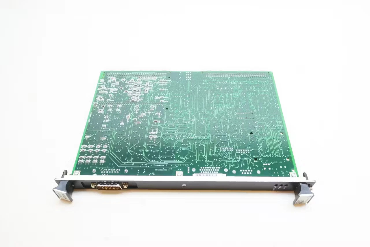
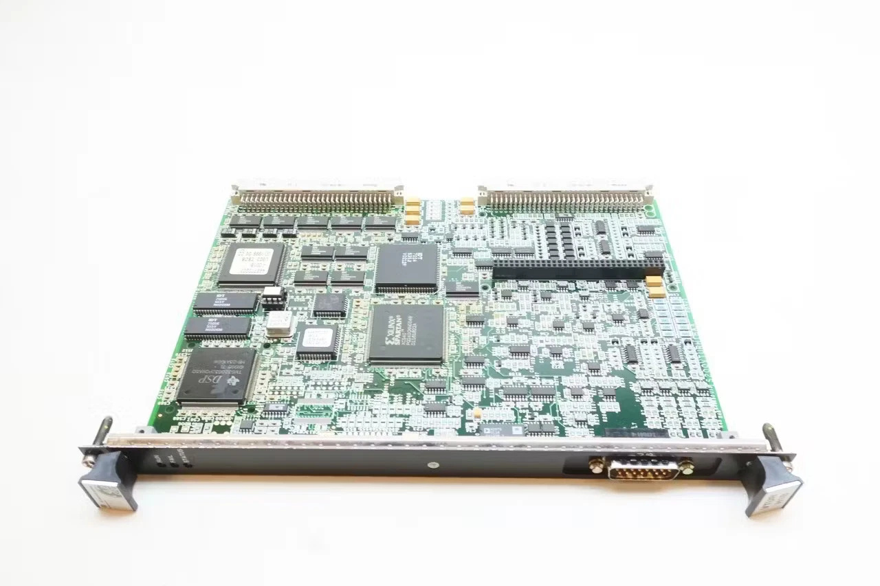
Ge IS200VTURH1BAA Printed Circuit Board
Ge IS200VTURH1BAA
1. Overview
2. Technical Specifications
- Operating Voltage: 24V DC
- Input Voltage Range: 24V DC (wide voltage compatibility for industrial environments)
- Maximum Current: Approximately 2A
- Operating Temperature Range: -40°C to 85°C (industrial-grade rugged design for extreme environments)
- Interface: Supports multiple input/output (I/O) signal connections, compatible with standard turbine monitoring points including speed, temperature, pressure, and vibration sensors
____________________________________________________________________________________________________________
3. Key Product Features
- Multi-Parameter Monitoring: Delivers comprehensive real-time monitoring of critical turbine operating metrics, including rotational speed, internal/external temperature, fluid pressure, and mechanical vibration. This full-scope monitoring ensures full visibility into turbine health and operational status at all times.
- High-Speed Response Capability: Optimized for high-frequency industrial applications, the PCB enables ultra-fast response to emergency conditions such as turbine overspeed and overcurrent events. Its rapid signal processing and actuation capabilities minimize response latency, preventing equipment damage and unplanned downtime.
- Superior Compatibility: Fully compatible with the GE Mark VI TMR (Turbine Mainframe) control system, offering seamless integration with a wide range of turbine controller models. This universal compatibility reduces retrofitting complexity and ensures consistent performance across diverse turbine setups.
____________________________________________________________________________________________________________
4. Structure & Components
- I/O Terminal Blocks: Dedicated connection terminals for secure wiring of external sensor signals and control loop circuits, ensuring stable signal transmission and anti-interference performance in harsh industrial settings.
- Logic Processing Circuitry: Built-in high-performance logic processing modules that execute real-time data analysis, logical judgment of input signals, and precise output of control commands. This core circuitry drives the card’s protective and regulatory functions with high accuracy.
- Built-In Safety Protection Mechanisms: Integrated comprehensive protection features including overcurrent protection, overvoltage protection, and short-circuit protection. These fail-safes shield the PCB and connected turbine equipment from electrical faults, enhancing overall system durability.
____________________________________________________________________________________________________________
5. Application Areas
- Power Station Turbine Control: Widely deployed in the main control systems of gas turbines and steam turbines, serving as a core protective component for power generation turbine assets in utility and industrial power stations.
- Power Plant Automation: Functions as an integral part of the GE Mark VI control system, seamlessly integrated into the automated control architectures of large-scale power plants. It supports end-to-end automated operation, monitoring, and protection for enhanced power generation efficiency and safety.
____________________________________________________________________________________________________________
6. Installation & Maintenance Guidelines
6.1 Installation Requirements
6.2 Installation Method
6.3 Maintenance Considerations
————————————————————————————————————-
If you would like to learn more about our products and services, please feel free to contact us at any time!
- Sales Manager : Jinny
- Email : sales5@xrjdcs.com
- Whatsapp/Mobile:+86 15359273791
Global renowned brand cooperation
ABB 丨 GE 丨Allen Bradley 丨 Honeywell 丨 Emerson 丨 Bently Nevada 丨 Westinghouse
Triconex 丨 Foxboro 丨 ICS Triplex 丨 Hima 丨 Schneider 丨 Yokogawa 丨 Woodward
—————————————————————————————
Industrial Control Products Detail Page
Product Range
- PLC Controllers: PLC controllers and peripheral equipment of brands such as ABB, Siemens, and Omron.
- DCS Systems: Spare parts for DCS systems of brands such as ABB, FOXBORO, and Honeywell.
- Inverters: Inverters of brands such as ABB, Siemens, and Yaskawa.
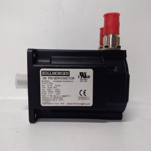
- Servo Motors: Servo motors of brands such as Yaskawa and Panasonic.
- Sensors: Sensors of brands such as ABB and Honeywell
- I/O Modules: I/O modules of brands such as ABB.
Customer Groups
- Petrochemical Industry
- Electric Power
- Iron and Steel
- Pharmaceutical Industry
- Food and Beverage
- Water Treatment
Our Advantages
- One-stop Procurement: We provide a wide variety of industrial control products to meet all your procurement needs.
- Professional Solutions: Our technical team will tailor the optimal solution for you.
- Considerate Service: We will provide you with pre-sales, in-sales and after-sales services throughout the whole process.