

ABB REJ525B 415BAA Fault Relay
ABB REJ525B 415BAA
1. Product Overview
2. Technical Parameters
|
Parameter Category
|
Specification of REJ525B 415BAA
|
|---|---|
|
Order Model
|
REJ525B 415BAA
|
|
Article Number
|
1MRS091415-BAA
|
|
I₀ Input Current Rating
|
1 A / 5 A
|
|
AC Auxiliary Supply Voltage
|
80…265 V ac (Rated: 110/120/220/240 V)
|
|
DC Auxiliary Supply Voltage
|
38…265 V dc (Rated: 48/60/110/125/220 V)
|
|
Rated Frequency
|
User-selectable 50/60 Hz
|
|
Ambient Temperature Range
|
Operation: -10…+55°C; Transportation/Storage: -40…+70°C
|
|
Input Channels
|
4 current inputs + 1 external binary input
|
|
Output Contacts
|
2 Power Outputs (PO1, PO2), 2 Signal Outputs (SO1, SO2), 1 Internal Fault Monitoring Output (IRF)
|
|
Conductor Size (X1 Current Input)
|
0.5…6.0 mm² (single-core) or max. 2.5 mm² (twin-core)
|
|
Conductor Size (X2 Terminal Block)
|
0.08…2.5 mm² (single-core) or max. 1.5 mm² (twin-core)
|
Reference Operating Time
- Overcurrent Start: Approx. 55 ms for low setting value, approx. 30 ms for high setting value
- Earth Fault Start: Approx. 60 ms for low setting value, approx. 40 ms for high setting value
3. Product Features
3.1 Protection Functions
- Overcurrent Protection: Three-phase low/high setpoint overcurrent protection (supporting definite time or inverse definite minimum time (IDMT) characteristics)
- Earth Fault Protection: Non-directional earth fault protection (supporting definite time or IDMT characteristics)
- Phase Failure Protection: Phase discontinuity unit
- Circuit Breaker Failure Protection (CBFP): Independent circuit breaker failure protection unit
- Inrush Current Identification Upon Closing: Automatically doubles setting values during startup
3.2 Recording and Data Storage
- Built-in disturbance recorder with a maximum recording duration of 10 seconds
- Supports recording of 4 analog channels and up to 8 digital channels
- Non-volatile storage: Event codes, configuration values, the latest five timestamped event data (up to 60 events in total)
3.3 Human-Machine Interface (HMI)
- Equipped with a 2×16 character LCD display
- Six control buttons for device operation
- Multi-language interface supported: English, German, French, Spanish, Italian, Swedish, Finnish
- Built-in user password protection function
3.4 Communication Capability
- Compatible with SPA bus and IEC 60870-5-103 protocol
- Front-panel optical PC connector for configuration tool connection
- Rear-panel RS-485 connector for system communication and optical fiber expansion
- Supports optical bus expansion (matched with RER 103 module)
3.5 Self-diagnosis and Maintenance Functions
- Real-time monitoring of electronic hardware and software operation status
- Automatic locking of all outputs in case of permanent faults
- Adopts isolated DC/DC converter for power supply
- All parameter settings editable via computer
- Alarm notification via HMI indicator LEDs and text messages
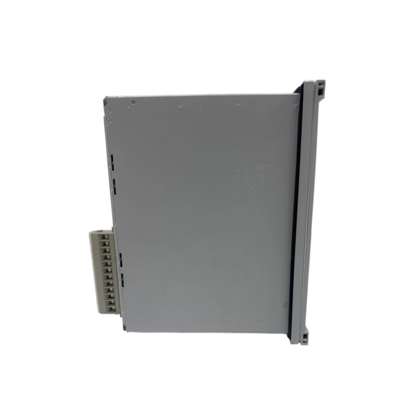
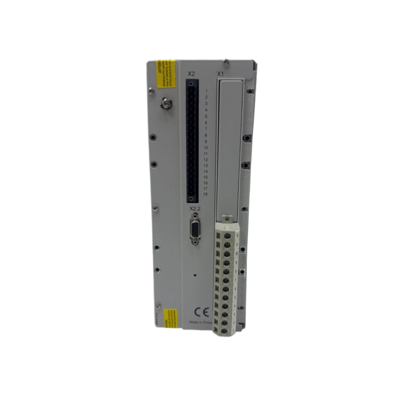
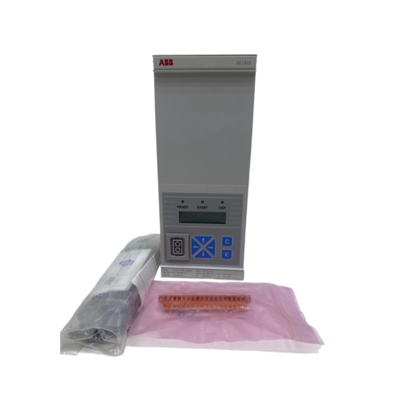
4. Structure and Composition
4.1 Hardware Structure
- Enclosure: Silver-gray metal compact enclosure, applicable to industrial automation scenarios
- Front Panel: Printed with ABB brand logo, product name and model number
- Status Indicators: Three LED indicators (READY, START, TRIP)
- LCD Screen: Displays device operating status and parameter data
- Control Panel: Equipped with cross directional keys and C/E function keys
- Power Port: Double-hole power interface on the left side
4.2 Wiring Terminal Definition
X1 Series (Current Input Terminals)
- Zero-sequence current (I₀): X1.1/1-3
- Phase current (In=5A): X1.1/4-5, 7-8, 10-11
X2 Series (Multifunctional Terminals)
- Auxiliary power voltage: X2.1/1-2 (DC/AC universal)
- Binary input: X2.1/17-18
- Communication port: Rear-panel RS-485 connector (D9S)
- Power/signal output and self-monitoring contacts: Connected to corresponding sockets on X2 terminal block
4.3 Optional Mounting Accessories
|
Accessory Type
|
Part Number
|
|---|---|
|
Rear Terminal Protection Cover
|
1MRS060132
|
|
Flush Mounting Kit
|
1MRS050209
|
|
Semi-flush Mounting Kit
|
1MRS050253
|
|
Wall Mounting Kit
|
1MRS050240
|
|
Side-by-side Mounting Kit
|
1MRS050241
|
|
19-inch Rack Mounting Kit
|
1MRS050257
|
|
Optical Bus Module RER 103
|
1MRS090701
|
|
Optical Coupling Cable
|
1MKC950001-1/2
|
5. Application Fields
- Application Scenario: Continuous overcurrent and earth fault monitoring on phase currents and neutral currents of electrical equipment
- System Matching: Compatible with substation automation and monitoring systems to complete circuit tripping, alarm triggering and fault data archiving tasks
- System Expansion: Flexible routing of cascaded protection signals via output contact matrix to realize scalable system layout
- Typical Application: Used as backup protection relay for medium-voltage distribution systems and substation protection solutions
6. Installation and Maintenance
6.1 Mounting Methods
- Flush Mounting: Suitable for standard cabinet installation
- Semi-flush Mounting: Partial protruding installation mode
- Wall Mounting: Fixed installation on wall surfaces
- Side-by-side Mounting: Parallel installation of multiple devices
- 19-inch Rack Mounting: Standard industrial rack installation
6.2 Wiring Requirements
- All current loops shall pass through test terminals to ensure stable contact performance
- Strong-current terminals and weak-current terminals shall be arranged separately; empty terminals or reinforced insulating partitions shall be adopted for isolation if separate arrangement is unavailable
- The primary side of power supply is protected by a 3.15A slow-blow fuse on the PCB board
6.3 Maintenance Guidelines
- Daily Monitoring: The built-in self-supervision system triggers alarms via HMI LEDs and text messages once faults occur during operation
- Power Inspection: Check fuse status regularly to ensure normal operation
- Parameter Backup: Back up all configuration parameters via computer periodically
- Communication Test: Test communication stability of optical port and RS-485 port regularly
- Standard Maintenance: Perform all maintenance operations in accordance with official product manuals
————————————————————————————————————-
If you would like to learn more about our products and services, please feel free to contact us at any time!
- Sales Manager : Jinny
- Email : sales5@xrjdcs.com
- Whatsapp/Mobile:+86 15359273791
Global renowned brand cooperation
ABB 丨 GE 丨Allen Bradley 丨 Honeywell 丨 Emerson 丨 Bently Nevada 丨 Westinghouse
Triconex 丨 Foxboro 丨 ICS Triplex 丨 Hima 丨 Schneider 丨 Yokogawa 丨 Woodward
—————————————————————————————
Cut Maintenance Costs – Optimize operations and reduce expenses with our high-quality, affordable automation replacement parts.
Always Available – Essential automation parts are constantly in stock, ensuring zero downtime for your operations.
24/7 Support – Our team is ready around the clock to assist with urgent needs and inquiries.
Fast Delivery – Ready stock enables quick dispatch and fast shipping, keeping your operations running smoothly.
100% Quality Assurance – Every part is strictly tested to ensure reliability and long-term performance.
Competitive Pricing & Outstanding Service – Exceptional service and unbeatable pricing maximize your value.
Choose us today for peace of mind, cost savings, and operational efficiency like never before!