Welcome to our websites!


GE 369-HI-R-M-0-0 Relay
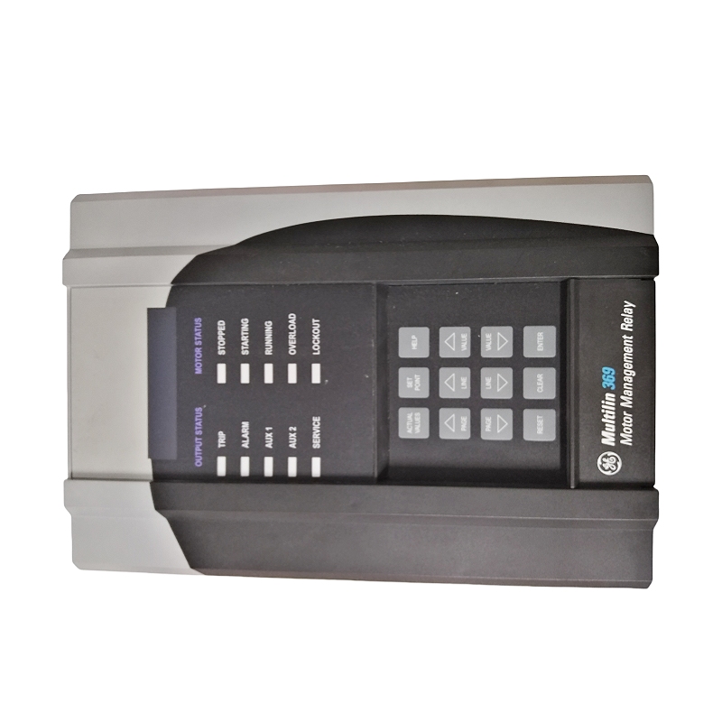
GE 369-HI-R-M-0-0
GE 369-HI-R-M-0-0 is a specific configuration model of the multi-functional, high-performance 369 Series Motor Protection Relays from General Electric (GE). Designed to provide comprehensive protection, monitoring, and control for medium and high-voltage three-phase induction or synchronous motors, this relay serves as a core device to ensure the safe, reliable, and efficient operation of critical rotating assets. GE 369-HI-R-M-0-0 integrates advanced microprocessor technology, enabling continuous monitoring of multiple motor parameters such as current, voltage, temperature, and power. Through its powerful logic functions, it implements complex protection algorithms. Not only can it quickly trip to prevent equipment damage when abnormal conditions like overload, short circuit, ground fault, locked rotor, current unbalance, or underload are detected, but it also provides abundant operating data and analysis tools. These tools assist users in predictive maintenance and energy efficiency management, thereby minimizing unexpected downtime and extending motor service life.
Product Parameters
- Product Model: 369-HI-R-M-0-0
- Manufacturer: General Electric (GE)
- Product Type: Motor Management Relay / Intelligent Motor Protector
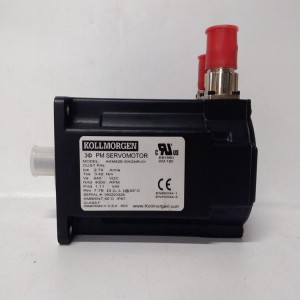
- Rated Input Current: 5A (derived from CT secondary side)
- Power Supply Voltage: 20 – 60 VDC / 20 – 265 VAC
- Protection Functions: Overload (inverse time), Short Circuit (instantaneous), Ground Fault, Current Unbalance, Locked Rotor, Underload, Under/Over Voltage, Stall
- Measured Parameters: Current, Voltage, Power, Power Factor, Electrical Energy, Frequency, Thermal Capacity Utilization
- Control Output: 2 Form C electromechanical relays (trip, alarm), optional 2 Form A solid-state relays
- Communication Protocol: Modbus RTU (RS-485), Modbus TCP/IP (Ethernet, optional module required)
- Display Interface: Backlit Liquid Crystal Display (LCD) for showing status, measured values, and fault information
- Ambient Operating Temperature: -40°C to +70°C
- Installation Method: Panel Mounting
Structure and Composition
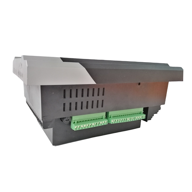
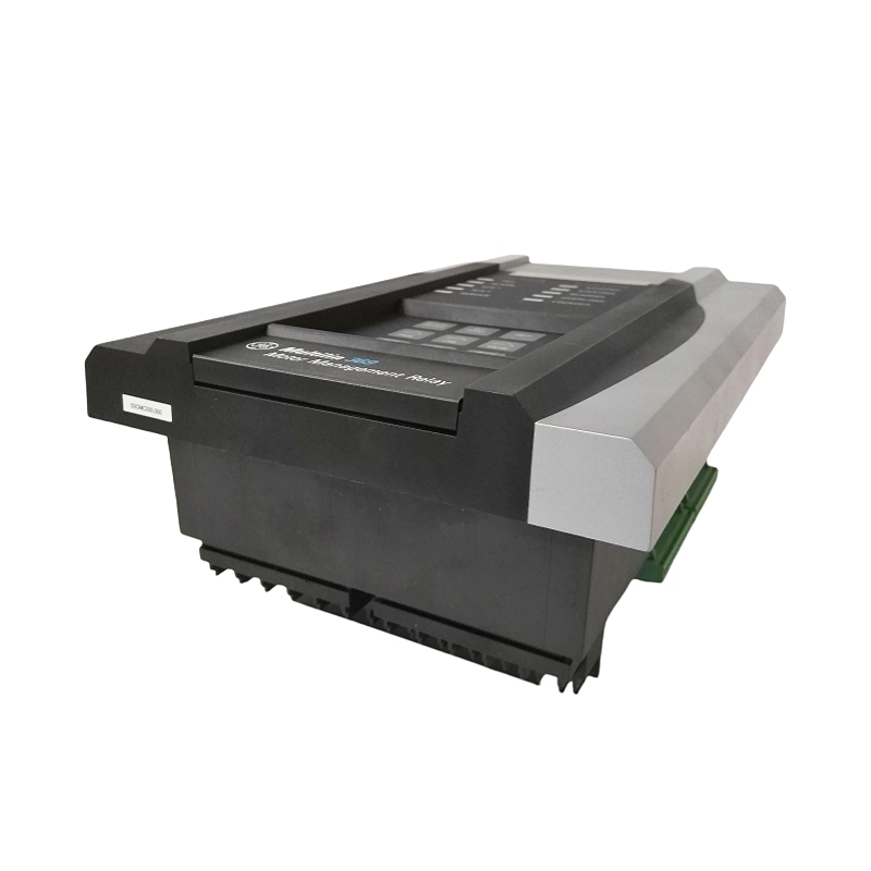
GE 369-HI-R-M-0-0 adopts a robust industrial-grade plastic housing. Its front panel integrates a high-contrast backlit LCD and navigation buttons, which are used for data viewing, parameter configuration, and event log checking. At its core is a high-performance microprocessor board, responsible for collecting all signals, performing calculations, and executing protection logic. On the input side, screw terminals are used to connect secondary side signals from Current Transformers (CTs) and Potential Transformers (PTs), as well as PT100 Resistance Temperature Detector (RTD) signals from the stator or bearings (optional). The output side provides programmable relay outputs for driving circuit breaker trip coils, alarm indicator lights, or control contactors. The -R- configuration of this model indicates that it is equipped with a standard RS-485 serial communication port, while -M- signifies that it has Modbus communication protocol functionality, allowing for easy integration into existing DCS or SCADA systems.
Key Features and Advantages
Comprehensive Motor Protection
GE 369-HI-R-M-0-0 offers one of the most comprehensive motor protection function suites in the industry. Its thermal model protection based on the I²t curve can accurately simulate the thermal characteristics of the motor, effectively preventing insulation aging. Advanced fault detection functions, such as sensitive ground fault protection and phase unbalance protection, can issue alarms or trigger trips before potential problems lead to catastrophic failures, providing all-round protection for the motor.
Advanced Monitoring and Diagnostics
Beyond basic protection functions, this relay acts as a powerful monitoring tool. It continuously records and displays key operating parameters, power quality, and thermal capacity usage, and can store time-stamped fault events and alarm logs. This provides maintenance teams with invaluable data for fault analysis, root cause identification, and predictive maintenance planning, transforming reactive maintenance into proactive maintenance.
Flexible Integration and Control
The standard Modbus RTU communication function enables 369-HI-R-M-0-0 to be seamlessly integrated into almost all automation systems. Users can remotely monitor motor status, modify set values, start/stop the motor, and receive alarm information in the control room, significantly improving operational efficiency and system integration. Its programmable logic inputs and outputs also offer high flexibility, which can be used to implement complex interlocking and control schemes.
Application Fields
GE 369-HI-R-M-0-0 is widely used in critical process industries that rely on medium and large-sized motors. In the oil and gas sector, it is used to protect pipeline pumps, compressors, and subsea injection pumps, ensuring production continuity and safety. In the water and wastewater treatment industry, it safeguards the safety of large pumps, aeration fans, and sludge conveyors. Additionally, in mining, chemical, pharmaceutical, and power generation plants (e.g., circulating water pumps, induced draft fans), as well as heating, ventilation, and air conditioning (HVAC) systems in large commercial buildings, 369-HI-R-M-0-0 is the preferred solution for protecting valuable motor assets and preventing production disruptions and significant economic losses caused by motor failures.
Installation and Maintenance
Pre-Installation Preparation
Before installing GE 369-HI-R-M-0-0, it is essential to ensure that all power supplies are disconnected and verified. Confirm that the secondary side of the Current Transformers (CTs) is reliably short-circuited until wiring is ready. Carefully read the manual and plan the protection set values based on the motor nameplate data and specific application requirements. Prepare appropriate tools and ensure the installation environment is clean and dry.
Maintenance Recommendations
Daily maintenance mainly involves regularly checking the relay display for alarm information and ensuring that the ventilation holes are not blocked. Periodically verify that the protection settings still meet the operating requirements. Utilize the relay’s built-in event logging and fault waveform capture functions (if supported) for post-fault analysis. After long-term operation, it is recommended that professionals conduct functional tests on the relay, simulating faults to ensure the normal operation of its trip logic and output contacts. Keep the firmware updated to the latest version.
————————————————————————————————————-

If you would like to learn more about our products and services, please feel free to contact us at any time!
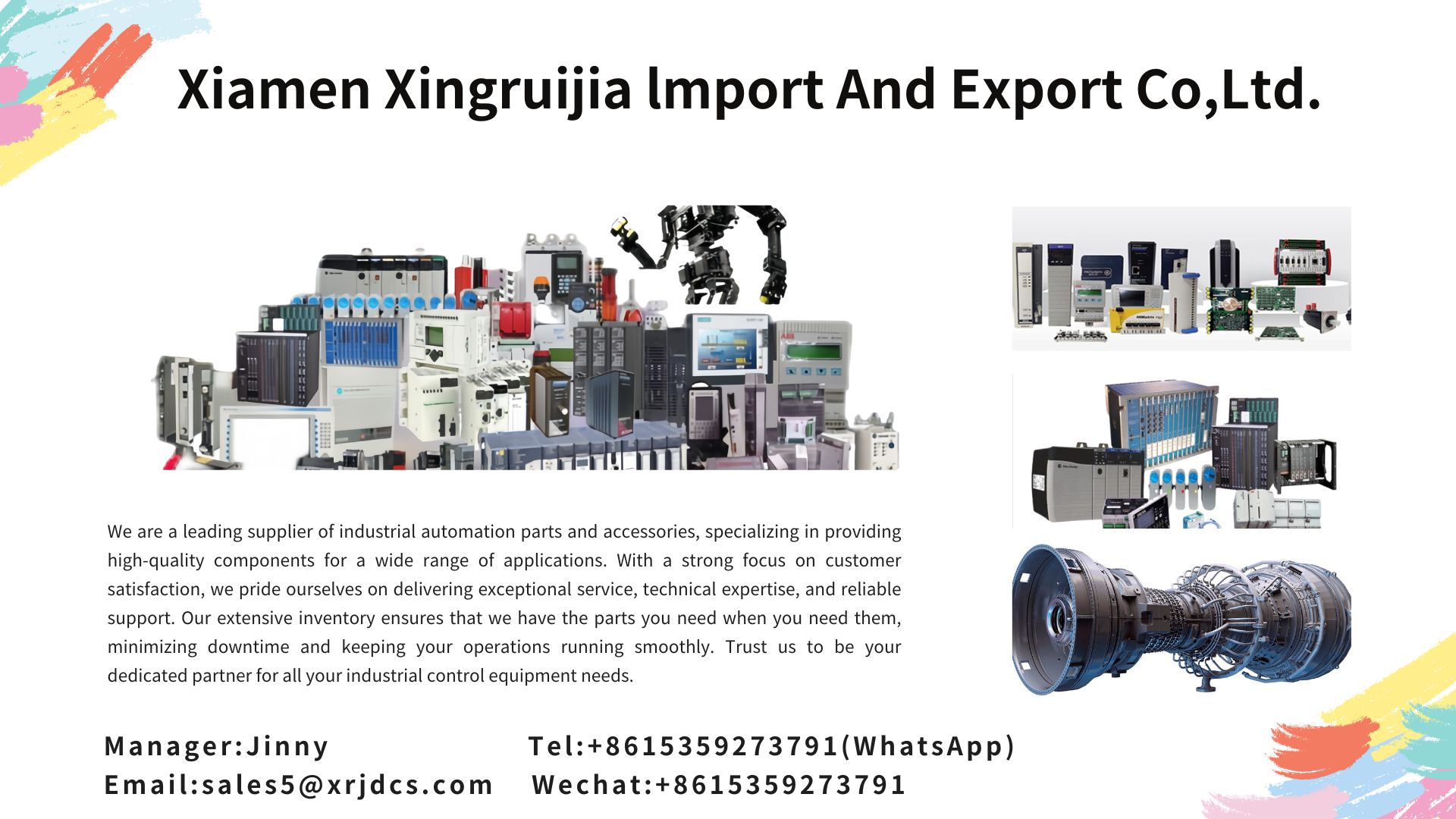
- Sales Manager : Jinny
- Email : sales5@xrjdcs.com
- Whatsapp/Mobile:+86 15359273791
Global renowned brand cooperation
ABB 丨 GE 丨Allen Bradley 丨 Honeywell 丨 Emerson 丨 Bently Nevada 丨 Westinghouse
Triconex 丨 Foxboro 丨 ICS Triplex 丨 Hima 丨 Schneider 丨 Yokogawa 丨 Woodward
—————————————————————————————
Core Product Range
Control & Signal Modules
- Central Control Units: PLC, DCS, CPU modules
- Interface & Communication Modules: Input/Output (AI/AO/DI/DO) modules, fiber optic interface boards, communication modules
- Functional Boards & Cards: I/O boards, counting boards, data acquisition cards, gas turbine cards, FIM cards, embedded cards
Drive & Peripheral Equipment
- Servo drives, servo motors
- Industrial displays, industrial keyboards
- Controllers, encoders, regulators, sensors
Power & Connection Components
- Power modules, thyristor modules, terminal modules
- Wires, cables, power modules, control modules
Our Competitive Advantages
- Industry Expertise & Inventory Strength: With long-term experience in the industrial control sector, we maintain a large stock of in-demand products to ensure fast delivery.
- Leading Market Position: We stand out with competitive pricing and strict quality control, guaranteeing reliable performance of all products.
- Comprehensive Product Coverage: Beyond standard models, we also supply rare and discontinued automation parts, meeting diverse customer needs.
- Assured After-Sales Service: Any product with quality issues can be replaced free of charge within 15 days of purchase, providing peace of mind for your operations.
Applicable Industries
Our automation spare parts are widely used in key sectors including:
Iron & steel, hydropower, nuclear power, power generation, glass manufacturing, tire factories, rubber production, thermal power generation, papermaking, shipping, navigation, and more.
Iron & steel, hydropower, nuclear power, power generation, glass manufacturing, tire factories, rubber production, thermal power generation, papermaking, shipping, navigation, and more.
Write your message here and send it to us