Welcome to our websites!


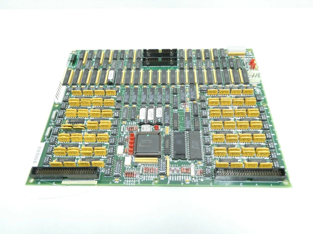
Ge DS200TCDAG1BCB I/O Circuit Board
Ge DS200TCDAG1BCB
The GE DS200TCDAG1BCB is a digital I/O printed circuit board (PCB) engineered exclusively by General Electric (GE) for the Mark V Speedtronic Turbine Control System. It is primarily deployed in industrial gas and steam turbine systems, delivering reliable management and control of relay outputs and contact inputs to support stable turbine operation.
1. Core Overview
Model Definition: The DS200TCDAG1BCB serves as a core digital I/O module within the GE Mark V series, tailored for high-performance industrial turbine control applications.
Primary Functions: Equipped with 16 channels of relay outputs and 16 channels of contact inputs, and integrated with an RS-232C communication interface for seamless data transmission.
Application Environment: Specially designed for use in industrial gas turbines, steam turbines, and other high-demand turbine control systems that require precision and reliability.
_______________________________________________________________________________________________________
2. Key Parameters & Specifications
|
Parameter
|
Specification
|
|---|---|
|
Input Voltage
|
24V DC
|
|
Output Voltage
|
24V DC
|
|
Relay Outputs
|
16 Channels
|
|
Contact Inputs
|
16 Channels
|
|
Communication Interface
|
RS-232C (Enabled/Disabled via Jumper J1)
|
|
Operating Temperature
|
-40℃ to 85℃
|
|
Protection Rating
|
IP20 (Must be installed in a well-protected enclosure/chassis)
|
|
Dimensions/Weight
|
Approx. 100mm × 50mm × 25mm, 200g
|
_______________________________________________________________________________________________________
3. Product Features
Redundant Design: Complies with stringent industrial safety standards, and is commonly used in redundant configurations to guarantee uninterrupted and safe turbine operation, minimizing downtime risks.
Flexible Hardware Configuration: Features onboard jumpers (J1-J8) for customizable settings, allowing users to disable IONET resistors, configure communication ports, and adjust other functional parameters based on on-site requirements.
Modular Architecture: Boasts a fully modular design for seamless compatibility and collaborative operation with other GE Mark V series boards, including STCA, UCPB, TCQA, TCQE, and TCEA modules.
_______________________________________________________________________________________________________
4. Structure & Components
Relay & Contact Modules: Integrated with 16 relay output channels and 16 contact input channels, enabling direct control of external hardware such as solenoid valves, switches, and other field devices.
Communication Module: Built-in RS-232C port (configurable for disable via onboard jumpers), facilitating stable data communication with host computers, PLCs, or other control units in the turbine control network.
Jumpers & Interfaces: Multiple hardware configuration jumpers for on-site parameter adjustment; connectors are positioned along the top and bottom edges of the board for convenient connection to racks or backplanes, simplifying installation and wiring.
_______________________________________________________________________________________________________
5. Typical Application Areas
Turbine Control Systems: Acts as a core component of the Mark V Speedtronic system, executing real-time control and monitoring for gas turbines and steam turbines in power generation and industrial processing facilities.
Industrial Automation: Widely applied in industrial process control scenarios that demand high-reliability digital I/O interfaces, ensuring stable and accurate signal transmission across automated production lines.
Safety Systems: Suitable for industrial and commercial safety applications, including fire detection systems, gas leakage monitoring, and other critical safety control scenarios requiring dependable I/O performance.
_______________________________________________________________________________________________________
6. Installation & Maintenance Recommendations
Installation Environment: Given the IP20 protection rating, the module must be installed in a sealed power distribution cabinet or equipment rack to prevent exposure to dust, moisture, liquids, and other harsh contaminants that may damage the board.
Power Supply Requirements: Ensure a stable 24V DC power supply; avoid voltage fluctuations, surges, or instability, as these can cause relay malfunctions, signal errors, or premature component failure.
Configuration Inspection: Before initial power-up, thoroughly check jumper settings (J1-J8) to verify that communication port configurations and IONET resistor setups align with on-site operational requirements, preventing system compatibility issues.
Routine Maintenance: Conduct regular inspections of physical wear on relay contacts and input terminals; clean or replace worn components promptly to maintain optimal signal transmission and extend the service life of the module.
————————————————————————————————————-
If you would like to learn more about our products and services, please feel free to contact us at any time!
- Sales Manager : Jinny
- Email : sales5@xrjdcs.com
- Whatsapp/Mobile:+86 15359273791
Global renowned brand cooperation
ABB 丨 GE 丨Allen Bradley 丨 Honeywell 丨 Emerson 丨 Bently Nevada 丨 Westinghouse
Triconex 丨 Foxboro 丨 ICS Triplex 丨 Hima 丨 Schneider 丨 Yokogawa 丨 Woodward
—————————————————————————————
Professional Industrial Control System Component Services & Core Advantages
Featured Services
Our company specializes in the supply of discontinued control system components and boasts exceptional inventory advantages. We maintain a large stock of surplus control system parts and discontinued hardware for control systems, ensuring reliable access to hard-to-find components. Additionally, we launch a wide range of new hardware and products to support your existing control systems or facilitate the adoption of cutting-edge control technologies.
We hold a dominant competitive edge in the supply of complete sets and accessories of discontinued DCS system spare parts, PLC module spare parts. No matter what type of PLC products you need, we can source them for you efficiently, and our company offers highly competitive pricing to maximize your cost savings.
Why Choose Us?
Partnering with our company grants you access to the following exclusive benefits:
- One-Stop Procurement: We offer an extensive range of industrial control products, covering all your procurement needs and simplifying your sourcing process to the fullest extent.
- Professional Custom Solutions: Our dedicated technical team develops tailored, optimal solutions based on your specific control system requirements and operational scenarios.
- Thoughtful Full-Cycle Service: We provide comprehensive pre-sales consultation, in-sales support, and after-sales service throughout the entire cooperation process, ensuring a hassle-free experience for every client.

Write your message here and send it to us