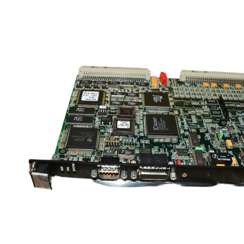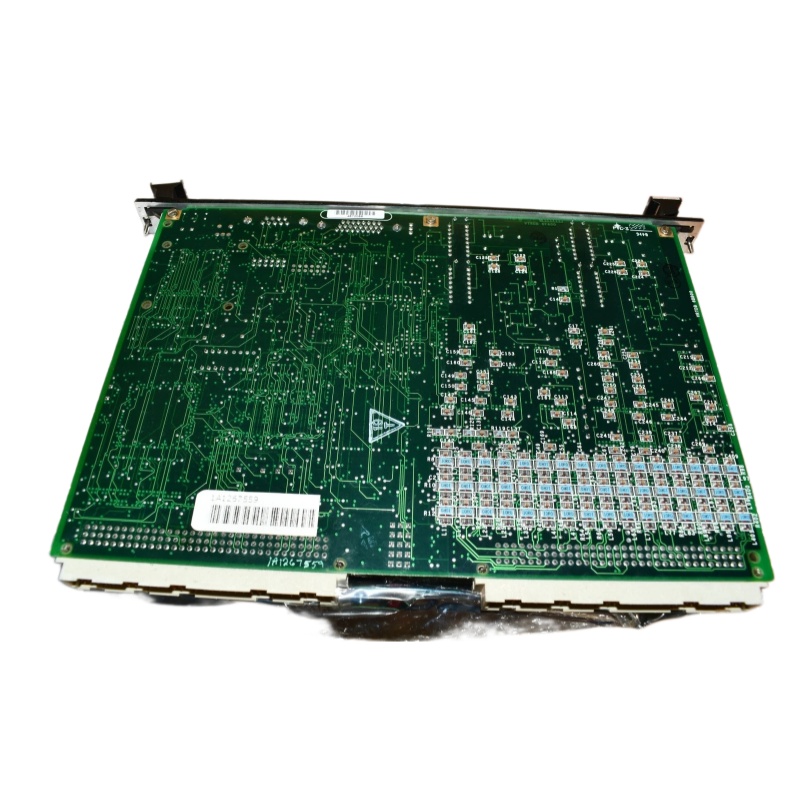
GE IS200VRTDH1B VRTD Board
GE Fanuc IS200VRTDH1B
1. Product Overview
2. Main Parameters and Technical Specifications
|
Item
|
Specification
|
|---|---|
|
Manufacturer
|
General Electric
|
|
Product Series
|
Mark VI Speedtronic™
|
|
Full Product Name
|
VME RTD Module / VRTD (Resistance Temperature Device Input Board)
|
|
Alternative Model / Equivalent Board Number
|
IS200VRTDH1BBA (Protective Coating Version)
|
|
RTD Input Channels
|
16 three-wire RTD inputs
|
|
Input Signal Range
|
Approximately 0.3532V to 4.054V
|
|
Current Excitation
|
10mA (supplied by VRTD board)
|
|
A/D Conversion Method
|
Implemented via sampling counter and voltage-to-frequency converter
|
|
Supported RTD Types
|
Supports linearization processing for 15 types of RTDs
|
|
On-board Components
|
Over 200 capacitors, hundreds of resistors, and more than 200 integrated circuits (including FPGA)
|
|
Front Panel I/O
|
37-pin latching D-Sub connector
|
|
LED Indicators
|
3 LEDs: Run (green flashing), Fault (red), Alarm (orange)
|
|
System Redundancy
|
Supports redundant design to prevent single-point failure
|
|
Detection Function
|
Supports RTD open-circuit and short-circuit detection
|
3. Product Features
4. Structure and Composition
5. Application Fields
6. Installation and Maintenance
————————————————————————————————————-
If you would like to learn more about our products and services, please feel free to contact us at any time!
- Sales Manager : Jinny
- Email : sales5@xrjdcs.com
- Whatsapp/Mobile:+86 18250705533
Global renowned brand cooperation
ABB 丨 GE 丨Allen Bradley 丨 Honeywell 丨 Emerson 丨 Bently Nevada 丨 Westinghouse
Triconex 丨 Foxboro 丨 ICS Triplex 丨 Hima 丨 Schneider 丨 Yokogawa 丨 Woodward
—————————————————————————————
Cut Maintenance Costs – Optimize operations and reduce expenses with our high-quality, affordable automation replacement parts.
Always Available – Essential automation parts are constantly in stock, ensuring zero downtime for your operations.
24/7 Support – Our team is ready around the clock to assist with urgent needs and inquiries.
Fast Delivery – Ready stock enables quick dispatch and fast shipping, keeping your operations running smoothly.
100% Quality Assurance – Every part is strictly tested to ensure reliability and long-term performance.
Competitive Pricing & Outstanding Service – Exceptional service and unbeatable pricing maximize your value.
Choose us today for peace of mind, cost savings, and operational efficiency like never before!