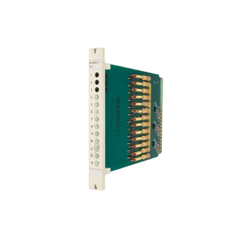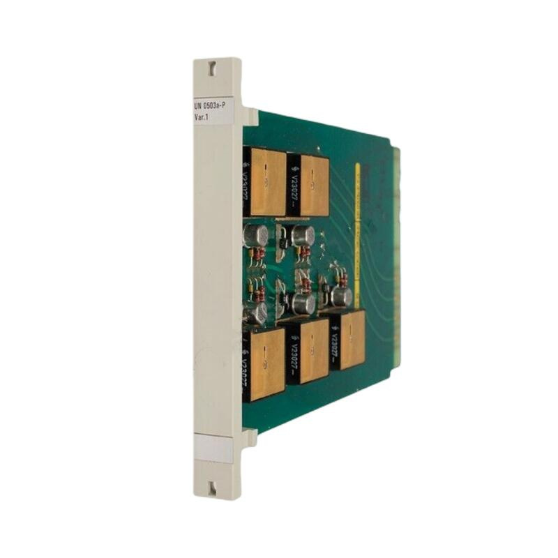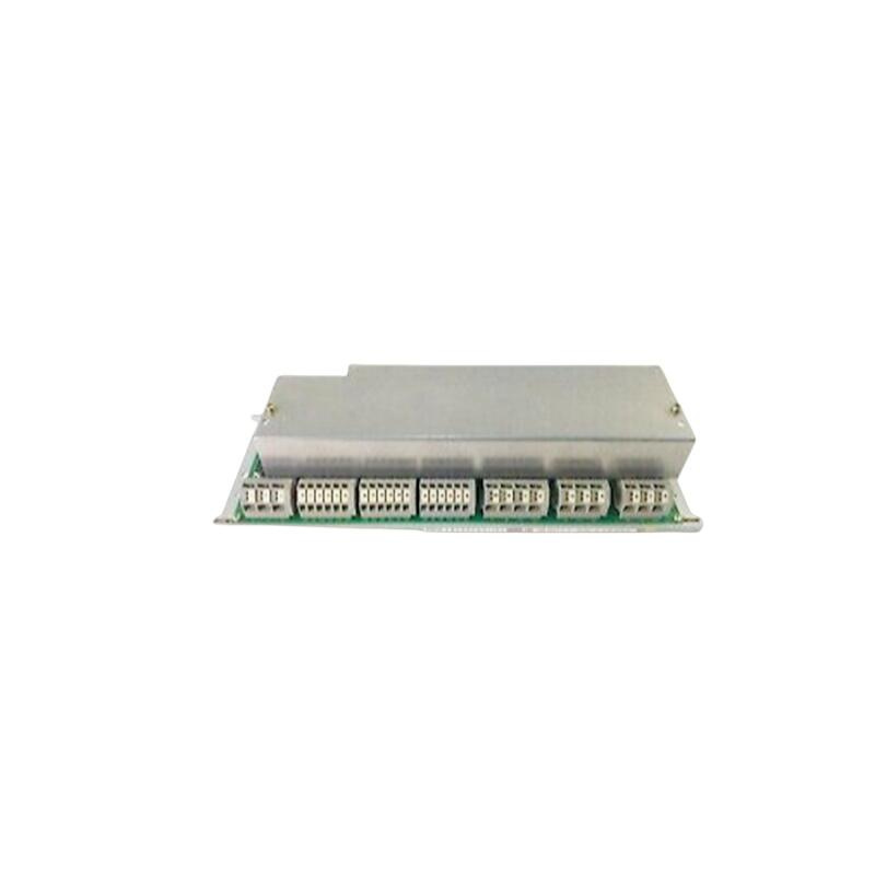
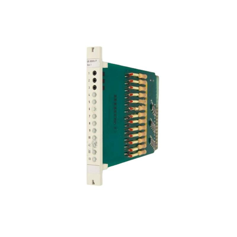
ABB UNS2881B-P.V1 Voltage Monitor Board
ABB UNS2881B-P.V1
Product Overview
The ABB UNS2881B-P.V1 is a compact, high-reliability voltage monitoring relay purpose-built for low-voltage and medium-voltage power distribution systems. As a critical protection component within ABB’s substation automation and motor control center (MCC) portfolios, it undertakes the continuous surveillance of single-phase or three-phase supply voltages, detecting overvoltage, undervoltage, phase loss, phase sequence reversal, and voltage asymmetry conditions with fast, deterministic tripping response.
This model belongs to ABB’s UNS series of system protection modules, widely deployed in original equipment manufacturer (OEM) switchgear and retrofit applications. Its encapsulated construction and wide operating temperature range make it suitable for both indoor substations and harsh industrial environments, including mining, marine, and heavy manufacturing facilities where power quality fluctuations are common. The relay output is a single Form C (SPDT) contact rated for 250 VAC / 5 A, directly capable of tripping circuit breakers, actuating alarm annunciators, or interlocking with motor starters without intermediate auxiliary relays.
Product Parameters
| Parameter Name | Parameter Value |
|---|---|
| Product Model | ABB UNS2881B-P.V1 |
| Manufacturer | ABB |
| Product Type | Voltage monitoring relay (fixed-threshold variant) |
| Nominal System Voltage | 208 VAC / 400 VAC / 480 VAC / 690 VAC (factory-configured per order) |
| Auxiliary Supply Voltage | 24–240 VAC/DC (wide-range universal input) |
| Overvoltage Trip Threshold | 110% of nominal (typical, fixed in P.V1 firmware) |
| Undervoltage Trip Threshold | 85% of nominal (typical, fixed in P.V1 firmware) |
| Phase Loss Detection | Yes (within 20% voltage drop on any phase) |
| Phase Sequence Detection | Yes (anti-clockwise / clockwise, configurable via hardware jumper) |
| Asymmetry Trip Threshold | ±5% of nominal (fixed) |
| Trip Delay Time | 0.1–10 seconds (selectable via DIP switch or factory-preset for P.V1) |
| Hysteresis (Reset Margin) | 2–5% of threshold (prevents contact chatter) |
| Measurement Principle | True RMS (for distorted waveforms) |
| Output Contact | 1 × SPDT (Form C), 250 VAC / 5 A resistive, 1/3 HP motor load |
| Output Contact Mode | Fail-safe (de-energized on fault or internal failure) |
| Accuracy (Voltage) | ±1% of setpoint (at 25°C) |
| Temperature Drift | ±0.1% / °C |
| Operating Temperature | –25°C to +70°C |
| Storage Temperature | –40°C to +85°C |
| Protection Degree | IP40 (front panel) / IP20 (terminals) |
| Mounting | DIN-rail (35 mm) or panel-mount (via adapter) |
| Dimensions (W × H × D) | 45 × 75 × 110 mm |
| Weight | Approx. 200 g |
| Certifications | CE, UL 508, CSA C22.2, RoHS compliant |
| MTBF (Mean Time Between Failures) | > 500,000 hours (at 40°C, per MIL-HDBK-217) |
Structure and Composition
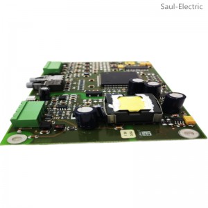
The ABB UNS2881B-P.V1 shares the fundamental hardware architecture of the UNS product platform, with the P.V1 version distinguished by factory-locked threshold settings and fixed timing parameters. Physically, the module is divided into three functional blocks: the input measurement and isolation stage, the logic decision core, and the output actuation stage.
The output actuation stage uses an electromechanical relay with a silver-alloy contact set, driven by a fail-safe control circuit. Under normal voltage conditions, the relay coil remains energized, holding the SPDT contact in the “healthy” position. Upon detection of any fault condition—or internal self-check failure—the coil de-energizes, causing the contact to transfer to the alarm/trip position. This “energized-to-run” design ensures that any loss of auxiliary power or internal failure results in a safe trip state, a fundamental requirement in power protection applications.
Key Features and Advantages
1. Factory-Preset, Plug-and-Protect Configuration
The most significant advantage of the UNS2881B-P.V1 is its fixed, factory-configured threshold set. Unlike adjustable relays that require skilled technicians to calibrate potentiometers and verify trip points with external test equipment, this version is delivered with thresholds, delays, and hysteresis precisely set to match the target nominal voltage (208/400/480/690 VAC). During switchgear assembly or field replacement, installers simply mount the unit, connect the phase and auxiliary power leads, and the relay is fully operational—no calibration, no testing, and no risk of misconfiguration. This eliminates a common source of protection scheme errors in high-volume panel production.
2. Comprehensive Fault Detection in One Compact Unit
The module simultaneously monitors for five distinct voltage anomalies: overvoltage (preventing equipment over-stress), undervoltage (preventing motor stall and overheating), phase loss (preventing single-phasing damage), phase sequence reversal (preventing reverse rotation of compressors and pumps), and voltage asymmetry (preventing transformer and motor derating). All are evaluated independently with dedicated comparators, ensuring that no fault type is overlooked even when multiple conditions occur simultaneously—a scenario often missed by simpler single-function relays.
3. True RMS Measurement for Non-Linear Power Environments
Modern industrial power systems frequently contain harmonic-rich currents and voltages caused by variable-frequency drives, UPS systems, and arc furnaces. Peak-sensing or average-sensing relays can produce measurement errors exceeding 30% under such conditions. The UNS2881B-P.V1′s true RMS converter delivers accurate readings regardless of waveform shape, ensuring that protection thresholds are evaluated against actual heating-equivalent voltage values—directly correlating with the thermal stress on motors, transformers, and cables.
4. Fail-Safe Design with Built-In Self-Diagnostics
The module continuously performs internal health checks on its power supply, measurement path, and comparator reference voltages. If any internal component drift or failure is detected, the relay output immediately transfers to the trip state. This behavior is verified during the power-up sequence: a momentary trip pulse is generated before the relay settles into normal operation, allowing system integrators to confirm the downstream alarm/trip path is intact. This self-check feature is particularly valued in nuclear, oil & gas, and critical process industries where silent failures are unacceptable.
5. Compact DIN-Rail Form Factor with Wide Auxiliary Supply
With a slim 45 mm width and universal 24–240 VAC/DC auxiliary supply, the module fits seamlessly into existing control panels without requiring a dedicated power transformer or voltage regulator. This simplifies retrofits in older installations where auxiliary supply availability may be limited. The wide supply range also accommodates fluctuations typical of industrial battery-backed DC systems or unregulated control transformers.
Application Fields
The ABB UNS2881B-P.V1 is deployed in a wide array of power distribution and motor control applications, primarily within ABB switchgear and MCC assemblies but also widely used as a standalone protection component in third-party panels.
The module also finds applications in shipboard power systems, offshore oil platforms, and mining operations, where its wide temperature range, conformal coated PCB option (available on certain P.V1 sub-variants), and robust vibration resistance make it a reliable choice for harsh marine and industrial environments.
Installation and Maintenance
Pre-Installation Preparation
Before installing the ABB UNS2881B-P.V1, ensure the monitored circuit is de-energized and properly locked out. Verify that the nominal system voltage printed on the unit’s side label matches the actual supply voltage to be monitored—the P.V1 variant is not field-adjustable, and applying a voltage higher than its rated threshold will cause continuous tripping or damage.
Electrical Connections
Connect the three phase monitoring inputs (L1, L2, L3) directly to the circuit breaker or supply bus via appropriately rated fuses or miniature circuit breakers (recommended 2 A, gG type) installed as close as possible to the tapping point. Use stranded copper wire with minimum cross-section of 1.5 mm² (16 AWG) for phase connections.
DIP Switch Configuration (Where Accessible)
The UNS2881B-P.V1 is factory-configured, but certain sub-variants allow limited field adjustment via a small DIP switch block accessible through a side cutout. If present, the switches typically control:
- Switch 1-2: Trip delay time (0.5 / 2 / 5 / 10 seconds)
- Switch 3: Phase sequence monitoring (enable/disable)
- Switch 4: Reset mode (automatic vs. latching)
Caution: Changing these settings from the factory-preset positions will deviate from the P.V1 specification. If the switch block is sealed with paint or covered by a sticker, field modification is not permitted—tampering will void the warranty and nullify type-test certifications.
Power-Up and Functional Check
After all connections are verified, re-energize the monitored circuit and auxiliary supply. Observe the front-panel LED indicator:
- Green steady: All voltage parameters are healthy.
- Flashing green: Normal operation but one parameter is near threshold margin (pre-alarm, if supported by variant).
- Red steady: Trip condition exists; check the monitored voltages for overvoltage, undervoltage, phase loss, or asymmetry.
- Red flashing: Internal module fault or auxiliary supply out of range.
Using a calibrated voltmeter, verify that the monitored phase voltages are within the acceptable range of nominal (defined by the P.V1 thresholds). Simulate a fault condition—e.g., temporarily disconnect one phase (using a test switch, if fitted) and confirm that the relay trips within the specified delay and that the output contact transfers. Reset the relay by restoring the voltage; if set to automatic reset, the contact should restore after the hysteresis margin is exceeded. If set to latching mode, a brief auxiliary power interruption may be required to reset.
Maintenance Recommendations
The UNS2881B-P.V1 is a solid-state monitored device with no user-serviceable internal components. Routine maintenance is limited to:
- Periodic visual inspection – Check terminal tightness (torque to 0.5–0.6 N·m) annually, particularly on phase input terminals subject to thermal cycling.
- Functional test – Perform a manual trip test every 12–24 months (or per plant PM schedule) by simulating undervoltage using a variable autotransformer or by using the test pushbutton, if fitted. Document the trip timing and reset behavior for condition monitoring trending.
- Cleaning – Use dry compressed air (low pressure) to remove dust accumulation from the enclosure louvers, ensuring adequate ventilation. Do not use solvents, as they may degrade the housing material and labeling.
- Diagnostic record – Where a communication-capable variant is deployed (RS-485 Modbus optional on some UNS models), retrieve the internal fault log and event counters during PM rounds. A rising trend in nuisance trip events may indicate power quality deterioration at the facility level rather than relay malfunction.
If you would like to learn more about our products and services, please feel free to contact us at any time!
- Sales Manager : Jinny
- Email : sales5@xrjdcs.com
- Whatsapp/Mobile:+86 18250705533
Global renowned brand cooperation
ABB 丨 GE 丨Allen Bradley 丨 Honeywell 丨 Emerson 丨 Bently Nevada 丨 Westinghouse
Triconex 丨 Foxboro 丨 ICS Triplex 丨 Hima 丨 Schneider 丨 Yokogawa 丨 Woodward
—————————————————————————————