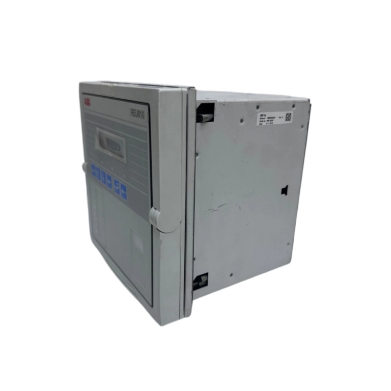

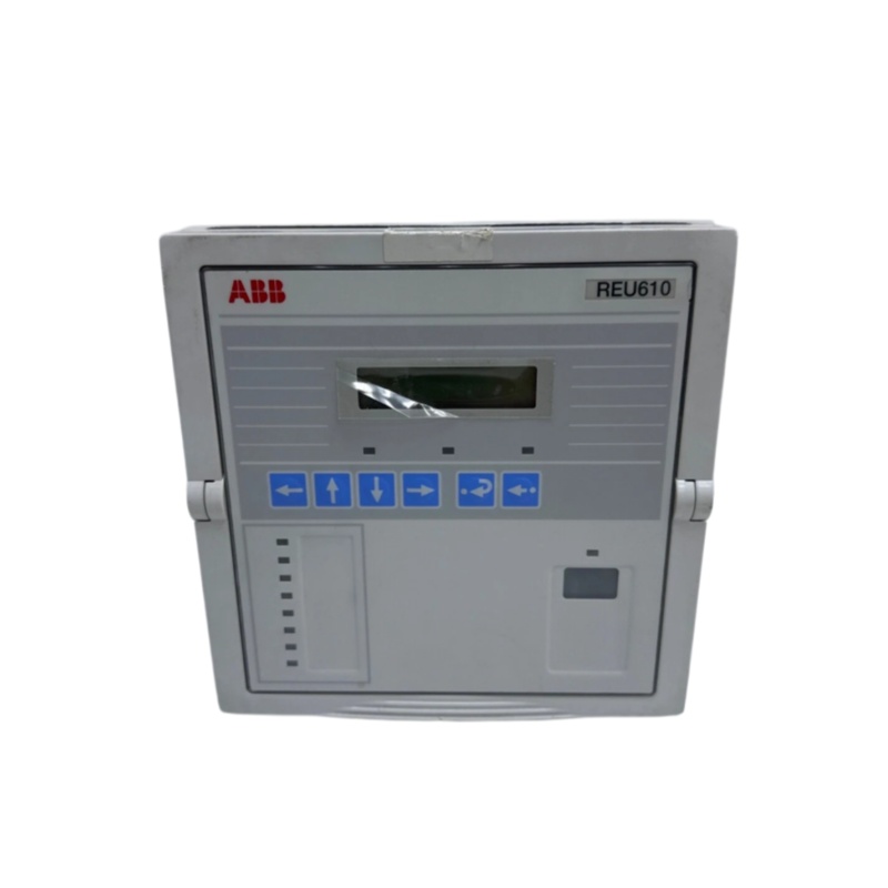
ABB REU610 REU610CVVHCHP Protective Relay
ABB REU610 REU610CVVHCHP
1. Product Overview
2. Technical Parameters
2.1 Protection Function Parameters
- Overvoltage Protection: Two-stage overvoltage protection
- Undervoltage Protection: Two-stage undervoltage protection
- Zero-sequence Voltage Protection: Two-stage residual overvoltage protection
- Negative-sequence Voltage Protection: Single-stage negative-sequence overvoltage protection
- Positive-sequence Voltage Protection: Single-stage positive-sequence undervoltage protection
2.2 Measurement Parameters
- Capable of measuring three-phase voltage and residual voltage
- Calculates positive-sequence and negative-sequence voltage values
- Calculates one-minute average phase voltage
- Calculates average phase voltage within user-specified time frames
- Records the maximum value of one-minute average voltage
- Records the maximum and minimum phase voltage values since the last device reset
2.3 Electrical Parameters
- Rated Frequency: 50/60Hz
- Voltage Input: 100/110/115/120 V (line-to-line voltage)
- Auxiliary Power Supply: 100-240 V AC / 110-250 V DC or 24-60 V DC
- Digital Inputs: 2 electrically isolated switch inputs (expandable to 5 channels)
- Digital Outputs: 2 normally open/normally closed signal output contacts (expandable to 5 channels)
2.4 Communication Interface
- Standard Interface: RS-485 interface, supporting plastic optical fiber, composite optical fiber and twisted pair cable
- Standard Protocols: SPA-bus, IEC60870-5-103, Modbus (RTU/ASCII mode)
- Optional Protocols: DNP3.0, IEC 61850, Profibus, LON
2.5 Recording Functions
- Disturbance Recording Duration: Up to 5 seconds
- Sampling Rate: 800Hz (adjustable)
- Analog Channels: 4 channels
- Digital Channels: Maximum 8 user-selectable switch channels
2.6 Physical Characteristics
- Dimensions: W164×H160×L149.3mm
- Installation Method: Plug-in design, panel snap-in installation
- Operating Temperature: 0℃ – +50℃
- Ambient Humidity: ≤85%RH
3. Product Features
3.1 High Safety and Reliability
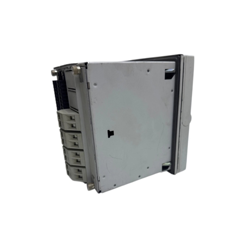
3.2 Optimized Plug-in Structure
3.3 Integrated Multi-function Design
3.4 Flexible Communication Compatibility
4. Structure and Composition
4.1 Front Panel Structure
- LCD Display: 2×16 character LCD screen with blue backlight for clear data display in various light environments
- Operation Keypad: Equipped with directional keys (up, down, left, right) and function keys for flexible parameter setting and device operation
- Status Indicators: Multi-row indicator lights to intuitively display real-time operating status and fault information
4.2 Main Body Structure
- Outer Casing: Compact rectangular metal casing with white finish, featuring corrosion resistance and strong structural stability
- Power Module: Flyback isolated three-level DC/DC converter, ensuring stable and efficient power supply
- I/O Module: Configurable digital and analog input/output modules to adapt to different functional requirements
- Communication Module: Optional configurable modules supporting multiple industrial communication protocols
4.3 Optional Accessories
- Semi-flush mounting kit
- Inclined semi-flush mounting kit
- Wall mounting kit
- 19-inch rack mounting kit
- Plastic optical fiber / RS-485 interface module
- DNP3.0 protocol communication module
If you would like to learn more about our products and services, please feel free to contact us at any time!
- Sales Manager : Jinny
- Email : sales5@xrjdcs.com
- Whatsapp/Mobile:+86 15359273791
Global renowned brand cooperation
ABB 丨 GE 丨Allen Bradley 丨 Honeywell 丨 Emerson 丨 Bently Nevada 丨 Westinghouse
Triconex 丨 Foxboro 丨 ICS Triplex 丨 Hima 丨 Schneider 丨 Yokogawa 丨 Woodward
—————————————————————————————
【Reasons to Choose us】
1. Unmatched Quality: Our products are sourced directly from top-tier foreign factories and undergo rigorous testing to ensure exceptional performance.
2. Your Satisfaction Guaranteed: Enjoy peace of mind with our one-year warranty and 15-day return or replacement policy for non-man-made issues.
3. Expert Support: Our 24/7 service hotline provides instant answers to your product questions.
4. Cost-Effective: Direct sourcing from manufacturers means competitive prices and a wide in-stock selection.
5. Fast Delivery: Experience quick shipping times thanks to our efficient supply chain.
————————————————————
【Delivery Time】
1. Express Shipping (DHL, UPS, FedEx, EMS):3-10 working days is a good rule of thumb. These services prioritize speed and often offer features like next-day or guaranteed dezlivery by a certain date (for an additional fee).
2. Air Mail (China Post, Hong Kong Post):7-35 working days, depending on the destination country. This is a more budget-friendly option, but it takes longer because it has lower priority for shipment.
【Important Notes】
Please follow the product’s instruction manual carefully for installation and debugging to avoid damage to the product.