Welcome to our websites!

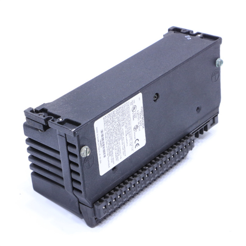
GE DS3800 DS3800HRRB1D1D Control System Components
GE DS3800 DS3800HRRB1D1D
1. Overview
The GE DS3800 Series serves as the core component of the Distributed Control System (DCS) exclusively designed by General Electric (GE) for industrial automation. Renowned for its high reliability, modular design, and multifunctional integration, this series of modules is widely deployed across industries including energy, manufacturing, and infrastructure.
______________________________________________________________________________________________
2. Key Parameters
- Operating Voltage: 24V DC (standard industrial voltage)
- Operating Temperature Range: -40℃ to 85℃, suitable for harsh industrial environments
- Communication Interface: Supports Ethernet and high-speed backplane communication, with millisecond-level failover capability
- Protection Grade: IP65, dustproof and waterproof
- Module Dimensions: Approximately 100mm × 50mm × 20mm (varies by specific model and functional module)
______________________________________________________________________________________________
3. Product Features
Modular Design
The modular architecture enables users to freely combine I/O channels, communication interfaces, and functional modules based on actual demands, facilitating quick assembly and later system expansion.
High Reliability
Constructed with industrial-grade components, the module supports dual redundant DC/DC power modules with 24V DC input. It is also equipped with built-in fault diagnosis and automatic switching functions, guaranteeing stable and uninterrupted system operation.
Multifunctional Integration
The module integrates signal conditioning (input), signal processing (CPU), and control output functions. It supports multiple communication protocols such as Modbus, Profibus, and EtherNet/IP, ensuring compatibility with diverse industrial systems.
Easy Maintenance
It comes with professional fault diagnosis functions, and a red LED indicator on the front panel displays real-time module status including power, communication, and fault conditions. Meanwhile, the modular structure greatly simplifies component maintenance and replacement.
______________________________________________________________________________________________
4. Structure and Composition
Signal Acquisition Layer
Responsible for input signal collection and preprocessing, this layer is generally equipped with photoelectric isolation and Schmitt triggers, supporting a wide 15-30V DC input voltage range.
Output Drive Layer
In charge of controlling actuators, this layer adopts magnetic latching relays or power modules, with output status indicated in real time via LED lights.
Communication and Power Layer
Handles data exchange with Mark IV controllers or host computers. This layer is fitted with dual redundant power modules, enabling millisecond-level fault switching to ensure continuous data transmission.
______________________________________________________________________________________________
5. Application Areas
The DS3800 Series modules are extensively used in scenarios requiring precise process control:
- Energy Industry: Process control for electric power, petroleum, and natural gas
- Manufacturing Industry: Automated production lines for automobiles, electronics, food processing, and other sectors
- Infrastructure: Management of public facilities such as water treatment and traffic control
______________________________________________________________________________________________
6. Installation and Maintenance Recommendations
Installation Environment
It is recommended to install the module in a ventilated, dry environment free of corrosive gases to ensure optimal heat dissipation (keep fans clean if equipped).
Power Connection
Connect the power supply strictly in accordance with the rated voltage (24V DC), and verify correct polarity to avoid module damage caused by reverse connection.
Communication Inspection
When connecting the backplane bus or Ethernet, check that connectors are securely inserted, and keep communication interfaces free of dust and looseness.
Fault Diagnosis
In case of abnormalities, first check the LED indicators on the module front panel (power, communication, and fault lights). Read fault codes via the system’s HMI or SCADA interface to locate the faulty module for replacement or repair.
————————————————————————————————————-
If you would like to learn more about our products and services, please feel free to contact us at any time!
- Sales Manager : Jinny
- Email : sales5@xrjdcs.com
- Whatsapp/Mobile:+86 15359273791
Global renowned brand cooperation
ABB 丨 GE 丨Allen Bradley 丨 Honeywell 丨 Emerson 丨 Bently Nevada 丨 Westinghouse
Triconex 丨 Foxboro 丨 ICS Triplex 丨 Hima 丨 Schneider 丨 Yokogawa 丨 Woodward
—————————————————————————————
Company Introduction
With 20 years of professional experience in large-scale imported systems, our company is engaged in the sales of spare parts for distributed control systems (DCS), programmable logic controllers (PLC), MOTOROLA MVME industrial modules, industrial control communication converters (Anybus), remote input/output modules (RTU), industrial personal computers (IPC), industrial low-frequency screens (IPC), human-machine interface SCSI (50, 68, 80 Pin), AnyBus (Gateway), redundant fault-tolerant control systems, and robot systems.
____________________________________________________________________________________________________________________
Our Advantages
Rich Product Line
We have a complete range of industrial control system equipment, which can meet the various needs of customers in different fields. Whether it is PLC, inverter, sensor, or other automatic control equipment, we can provide professional solutions.
High-Quality Service
We have an experienced team that can provide customers with comprehensive services from product selection, technical support to after-sales service. We always adhere to customer-centricity and create maximum value for customers.
Stable Supply Chain
We have established long-term and stable cooperative relationships with many world-renowned brands, which can ensure the authenticity and stable supply of products.
Professional Technical Support
Our technical team has rich industry experience and can provide customers with professional technical consulting and solutions.
Write your message here and send it to us