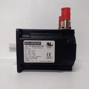
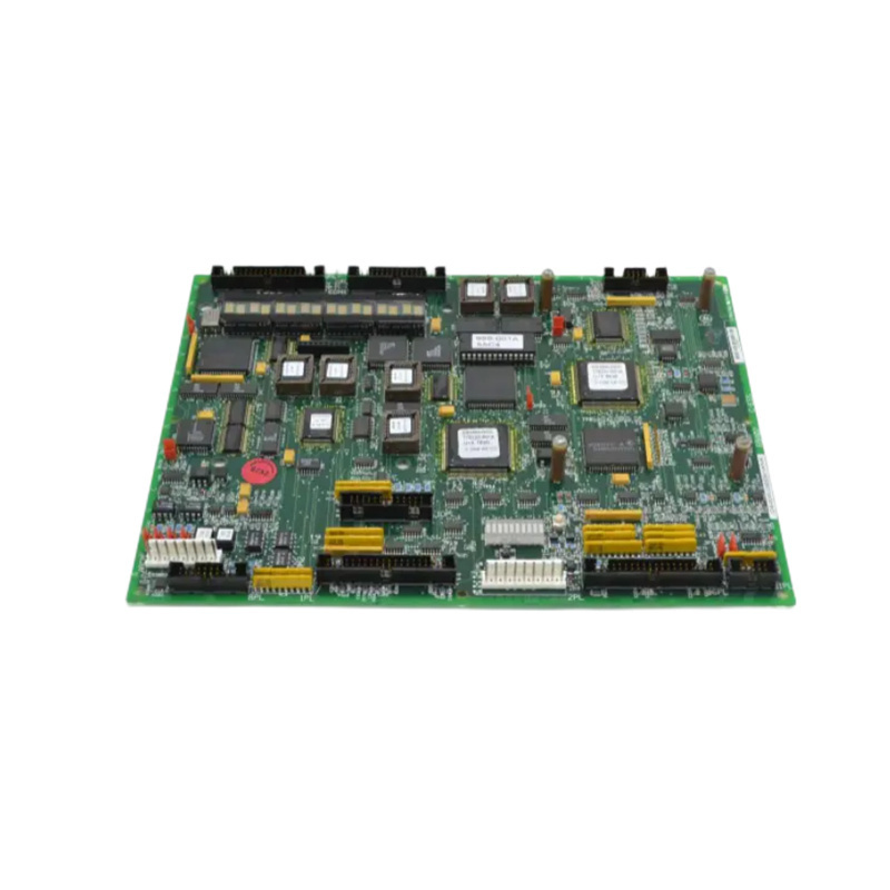
GE IS200EDFFH1A I/O Terminal Board
GE IS200EDFFH1A
1. Overview
2. Technical Parameters
|
Parameter Item
|
Specification / Description
|
|---|---|
|
Power Supply Voltage
|
28V Direct Current (DC)
|
|
Circuit Type
|
V-F (Voltage-to-Frequency) Converter Circuit
|
|
Signal Conversion
|
Converts field voltage and field current into frequency feedback signals
|
|
Isolation Technology
|
Fiber optic interface provides voltage isolation and high noise immunity
|
|
Series Affiliation
|
High-voltage interface component of the EX2100e series
|
3. Product Features
4. Structure and Composition
5. Application Fields
6. Installation and Maintenance
6.1 Installation Guidelines
6.2 Maintenance Precautions
If you would like to learn more about our products and services, please feel free to contact us at any time!
- Sales Manager : Jinny
- Email : sales5@xrjdcs.com
- Whatsapp/Mobile:+86 15359273791
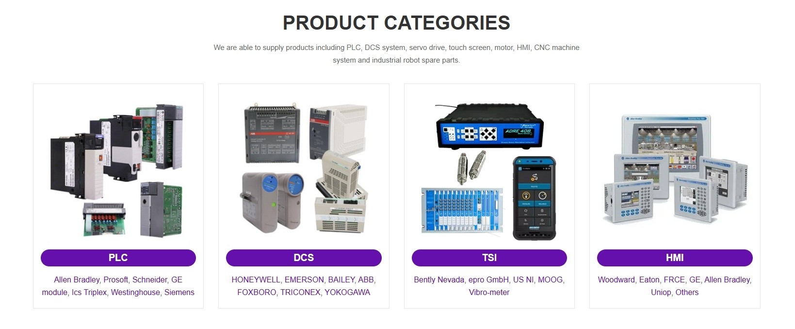
Global renowned brand cooperation
ABB 丨 GE 丨Allen Bradley 丨 Honeywell 丨 Emerson 丨 Bently Nevada 丨 Westinghouse
Triconex 丨 Foxboro 丨 ICS Triplex 丨 Hima 丨 Schneider 丨 Yokogawa 丨 Woodward
—————————————————————————————
【Reasons to Choose us】
1. Unmatched Quality: Our products are sourced directly from top-tier foreign factories and undergo rigorous testing to ensure exceptional performance.
2. Your Satisfaction Guaranteed: Enjoy peace of mind with our one-year warranty and 15-day return or replacement policy for non-man-made issues.
3. Expert Support: Our 24/7 service hotline provides instant answers to your product questions.
4. Cost-Effective: Direct sourcing from manufacturers means competitive prices and a wide in-stock selection.
5. Fast Delivery: Experience quick shipping times thanks to our efficient supply chain.
————————————————————
【Delivery Time】
1. Express Shipping (DHL, UPS, FedEx, EMS):3-10 working days is a good rule of thumb. These services prioritize speed and often offer features like next-day or guaranteed dezlivery by a certain date (for an additional fee).
2. Air Mail (China Post, Hong Kong Post):7-35 working days, depending on the destination country. This is a more budget-friendly option, but it takes longer because it has lower priority for shipment.
【Important Notes】
Please follow the product’s instruction manual carefully for installation and debugging to avoid damage to the product.